Prognostic cell for predicting failure of integrated circuits

Inactive Publication Date: 2007-09-18
RIDGETOP GROUP
View PDF8 Cites 78 Cited by
  • Summary
  • Abstract
  • Description
  • Claims
  • Application Information

AI Technical Summary

Benefits of technology

[0013]In an exemplary embodiment, the prognostic cell comprises a test device having a test component, a coupling circuit that couples the operational stress applied to the useful circuit to the test device, and a stress circuit that increases the operational stress to accelerate deterioration of the test component. A comparison circuit compares a performance characteristic of the test component to a baseline, determines whether the test component has failed and generates the failure indicator. In certain embodiments, the baseline is provided by a reference device that is subjected to reduced operational stress. To reduce statistical variation in the failure indicator, the prognostic cell may use a plurality of test devices to oversample the underlyin

Problems solved by technology

All manufactured products have non-zero failure probability, that is, there is at every instance of use a certain probability that the product will fail.
A particular product line's failure rate is the number of such products that is expected to fail per unit time.
However, worst-case conditions are typically poorly defined and are usually not continuously present.
Therefore, a

Method used


Image

  • Prognostic cell for predicting failure of integrated circuits
  • Prognostic cell for predicting failure of integrated circuits
  • Prognostic cell for predicting failure of integrated circuits

Examples


Embodiment Construction

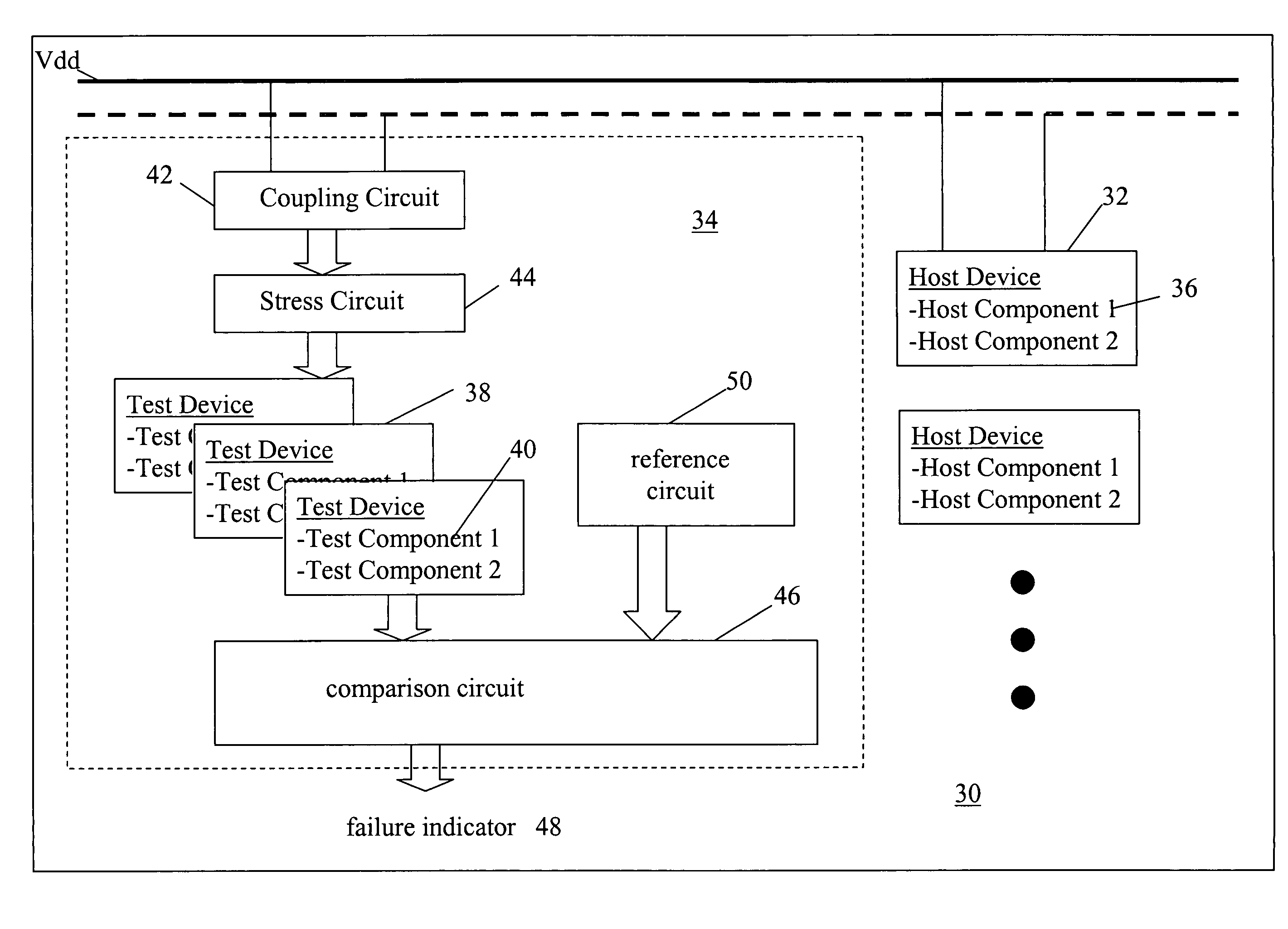
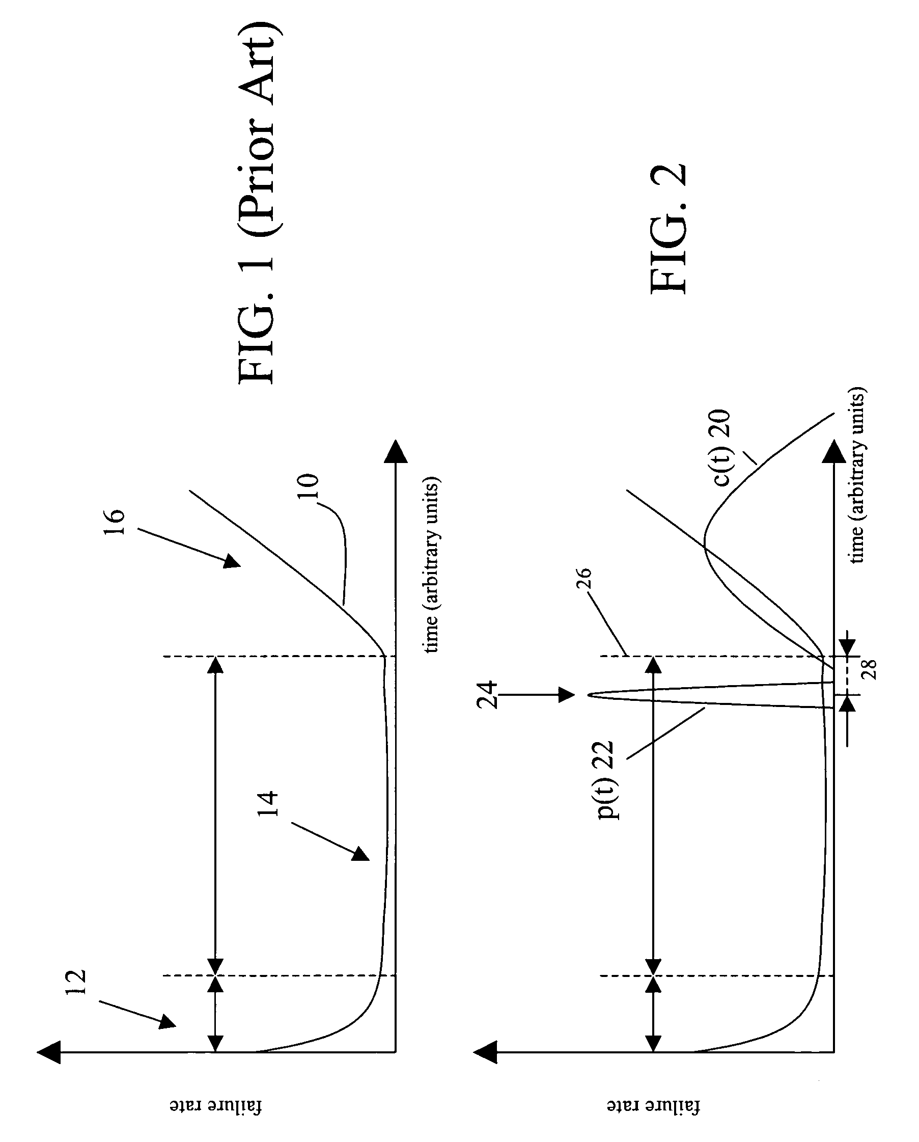
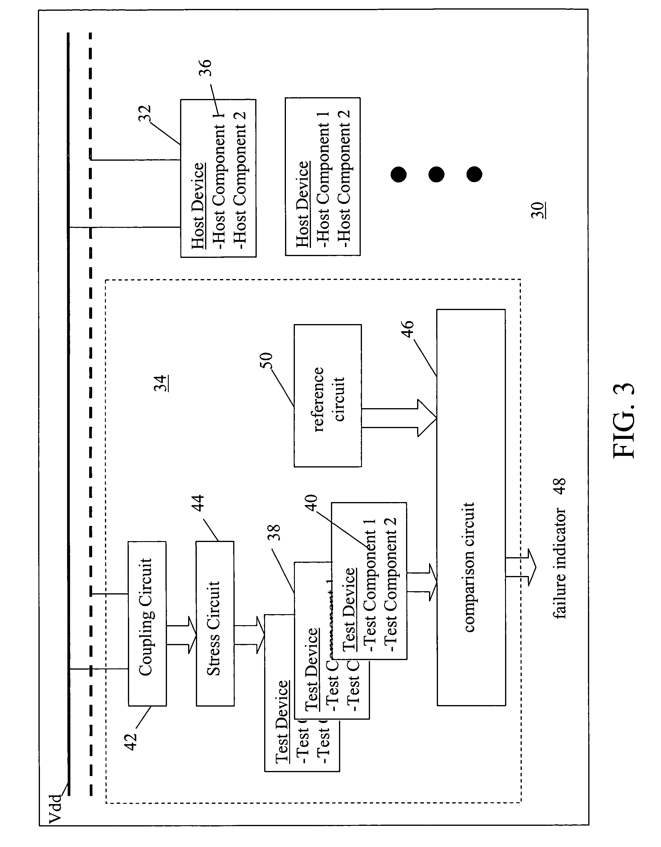
[0035]The present invention provides a prognostic cell to predict impending failure (complete failure or degradation outside a specified region of operation) of a useful circuit or circuits in a host IC. Increasing the use or environmental stress on the prognostic cell relative to the useful circuit, shifts the failure distribution of the cell along the time axis. The relative amount of time between the useful circuit failure and prognostic cell trigger point is the “prognostic distance”. The prognostic distance of the prognostic cell is controlled by designing in the excess stress applied in test device(s), by setting the threshold for triggering in the comparison circuit or by both. The amount of excess stress and / or the threshold setting required can be determined using statistical modeling and measurement data. Prediction accuracy is enhanced by oversampling, i.e. using multiple test devices and setting the trigger point when a certain fraction fails.

[0036]As shown in FIG. 2, th...


PUM


Abstract

A prognostic cell is used to predict impending failure of a useful circuit or circuits in a host IC. Increasing the stress on the prognostic cell relative to the useful circuit shifts the failure distribution of the cell along the time axis. The relative amount of time between the useful circuit failure and prognostic cell trigger point is the “prognostic distance”. The prognostic distance is controlled by designing in the excess stress applied in test device(s), by setting the threshold for triggering in the comparison circuit or by both. Prediction accuracy is enhanced by using multiple test devices to oversample the underlying failure distribution and triggering the failure indicator when a certain fraction fail.

Description

CROSS-REFERENCE TO RELATED APPLICATIONS[0001]This application claims benefit of priority under 35 U.S.C. 119(e) to U.S. Provisional Application No. 60 / 428,655 entitled “Method for making semiconductor reliability indicator cells” filed on Nov. 25, 2002, the entire contents of which are incorporated by reference.BACKGROUND OF THE INVENTION[0002]1. Field of the Invention[0003]This invention relates to integrated circuits (ICs) and more specifically to a prognostic cell capable of predicting impending failure of a useful circuit on the IC.[0004]2. Description of the Related Art[0005]All manufactured products have non-zero failure probability, that is, there is at every instance of use a certain probability that the product will fail. A particular product line's failure rate is the number of such products that is expected to fail per unit time. The failure rate is thus equivalent with the failure probability.[0006]The failure probability during the life of a manufactured product typical...

Claims


Application Information

Patent Timeline
IPC IPC(8): G01R31/02
CPCG01R31/2856G01R31/2879
Inventor VERMEIRE, BERT M.PARKS, HAROLD G.GOODMAN, DOUGLAS L.
Owner RIDGETOP GROUP
Why Eureka
Try Eureka