Delay-locked loop having a plurality of lock modes

a delay-locked loop and lock mode technology, applied in the direction of electrical equipment, pulse automatic control, etc., can solve the problems of dll effectively losing lock, temperature can change significantly, and dll cannot continue to compensate for temperature variations

Active Publication Date: 2007-09-18
MEDIATEK INC
View PDF5 Cites 59 Cited by
  • Summary
  • Abstract
  • Description
  • Claims
  • Application Information

AI Technical Summary

Benefits of technology

[0010]In another embodiment a delay-locked loop circuit is provided that includes a delay line circuit having a controllable delay. A phase detector circuit is coupled to compare a reference signal with a feedback signal of the delay-locked loop circuit and supply one or more signals indicative of the comparison. A counter circuit is coupled to the one or more signals from the phase detector circuit. An initial increment value for the counter while locking to the reference signal varies according to which lock mode of a plurality of lock modes is selected.

Problems solved by technology

However, a frozen DLL cannot continue to compensate for temperature variations.
If the memory controller is in a low power state for a long time, the temperature can change significantly and the DLL effectively loses lock.
However, that approach may result in false locks that need to be guarded against.

Method used


Image

  • Delay-locked loop having a plurality of lock modes
  • Delay-locked loop having a plurality of lock modes
  • Delay-locked loop having a plurality of lock modes

Examples


Embodiment Construction

)

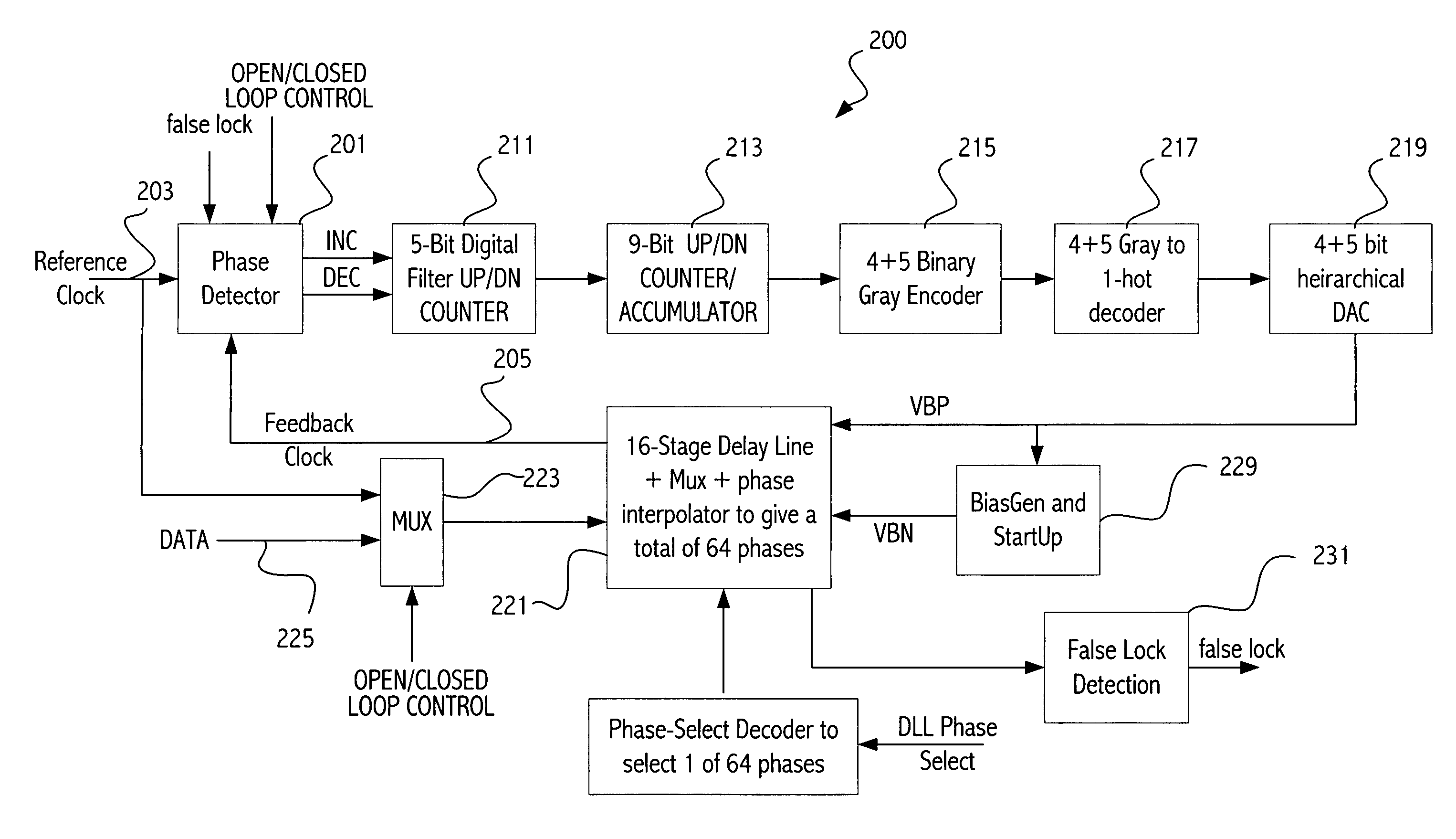
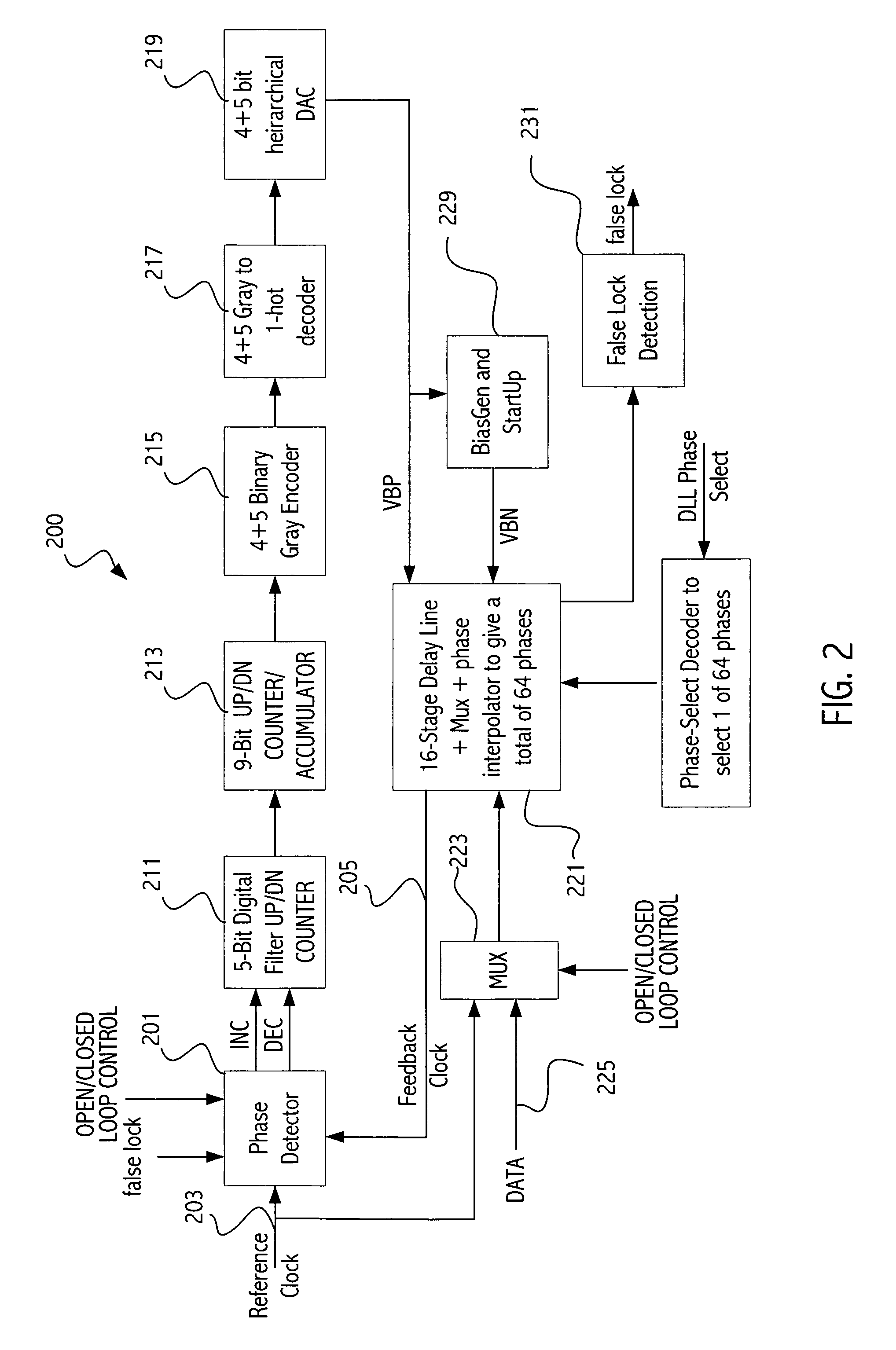
[0031]A delay-locked loop (DLL) can be used to create an arbitrary phase delay with respect to a reference clock and can compensate for process, voltage, and temperature (PVT) variations in integrated circuits. In high speed interfaces, e.g., the DDR2 memory interface, a robust delay-locked loop (DLL) having low jitter and offset is important for both receive and transmit timing. In an embodiment, the DDR2 interface requires digitally programmable phase delays of clock-period*N / 64 of a reference clock, where N in an integer and could be anywhere from 1 to 64

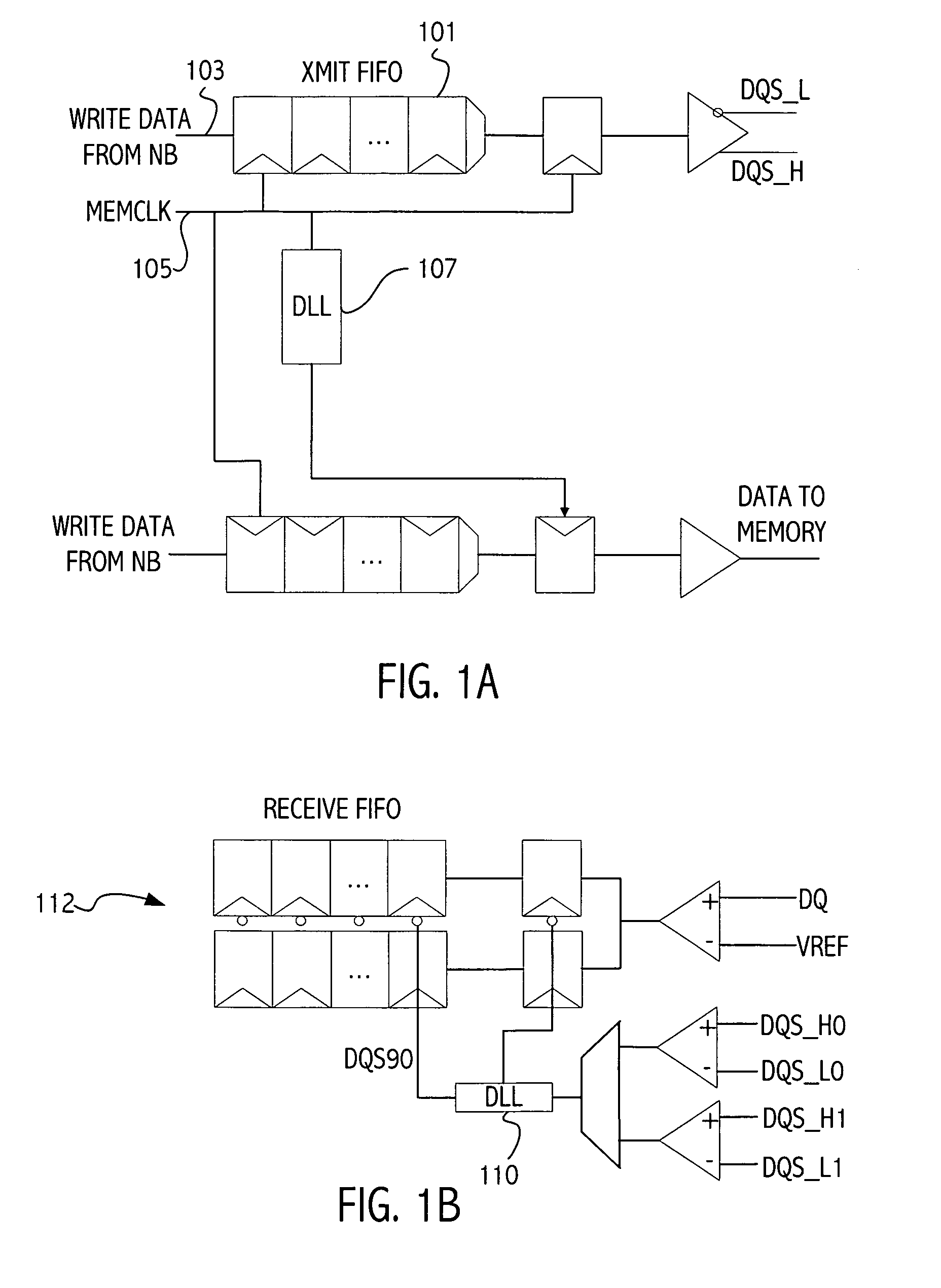
[0032]Referring to FIG. 1A, an exemplary memory interface is shown in which an embodiment of the invention can be utilized. Outbound data is written into a transmit FIFO 101 using a source synchronous data path 103. In one embodiment the MEMCLK 105 is used as the reference clock for all outbound signals. In some embodiments a portion of the memory interface is located in a separate voltage plane from other portions of the integr...


PUM


Abstract

A delay-locked loop (DLL) has a counter that is incremented or decremented by the loop in the process of achieving lock. The counter value is converted using an digital to analog converter (DAC) to an analog voltage that controls the delay through the delay line. During faster lock modes, the loop increments/decrements intermediate bits of the counter (with the bits less significant being held at a constant value, e.g., 0) to provide a coarse lock, rather than incrementing/decrementing the least significant bit of the counter. After coarse lock is achieved, a better lock is then achieved by incrementing/decrementing the counter using a smaller increment, i.e., a less significant bit is updated, until finally, the LSB is utilized to achieve fine lock. Utilizing the coarse lock first, and then one or more finer locks, allows the lock to be achieved more quickly.

Description

CROSS-REFERENCE TO RELATED APPLICATION(S)[0001]This application claims the benefit under 35 U.S.C. § 119(e) of application No. 60 / 718,014, filed Sep. 16, 2005, which application is incorporated herein by reference.BACKGROUND[0002]1. Field of the Invention[0003]This application is directed to delay-locked loops.[0004]2. Description of the Related Art[0005]High speed memory interfaces employ delay lines to position data with respect to clock or clocks with respect to data to meet system timing requirements. A delay line typically includes a series of delay cells, where the delay through each cell can be varied. Delay lines can be configured in a delay-locked loop (DLL), which automatically adjusts the voltage / current in the delay cell, so that the total delay of the delay line tracks the frequency of a reference signal supplied to the DLL. When the delay line supplies an output signal having the desired frequency and phase, the DLL is said to be locked.[0006]High accuracy may be requi...

Claims


Application Information

Patent Timeline
Patent Type & Authority Patents(United States)
IPC IPC(8): H03L7/06
CPCH03L7/0812H03L7/093H03L7/0818H03L7/0814
Inventor DAGA, ANANDSETHI, SANJAYMADRID, PHILIP E.
Owner MEDIATEK INC
Why Eureka
Try Eureka