
Digital television receiver with automatic gain control unit and method

a digital television and receiver technology, applied in the field of digital television, can solve the problems of degrading tracking response, adding to the already non-linear response inherent in practical agc systems, and broadcasting of vsb signals susceptible to multipath interferen

Active Publication Date: 2007-09-18
SAMSUNG ELECTRONICS CO LTD
View PDF7 Cites 15 Cited by
  • Summary
  • Abstract
  • Description
  • Claims
  • Application Information

AI Technical Summary

Benefits of technology

This solution enhances signal tracking performance by improving dynamic range by about 12 dB and reducing gain fluctuation up to 8 dB, enabling stable acquisition and tracking of VSB signals in high-noise multipath channels with reduced distortion.

Problems solved by technology

It is known that broadcasts of VSB signals are susceptible to multipath interference, such as interference from multiple signals arriving at an antenna at different times due to obstacles such as buildings and vehicles.
First, the control over amplifiers that have different transfer function characteristics, with a common controlling arm, will result in degraded tracking response, adding to the already non-linear response inherent in practical AGC systems.
Demodulation blocks whose operations are limited and not stable will compromise the performance of the AGC.
Other schemes involve the use of signals at the matched filter upward or the equalizer output for decision directed feedback buffer from multi-path interference discussed above, since the coherency of the reference signals cannot always be considered good references for gain control.
In addition, the delayed demodulator response prohibits the use of coherent mode of operation with the already time-delayed tuner response that is non-linear.
However, if the RF and IF amplifiers are commonly controlled, even with dual AGCs, the non-linear error characteristics of the amplifiers may be difficult to correct, especially if fixed reference levels are used.

Method used


Image

  • Digital television receiver with automatic gain control unit and method
  • Digital television receiver with automatic gain control unit and method
  • Digital television receiver with automatic gain control unit and method

Examples


Embodiment Construction

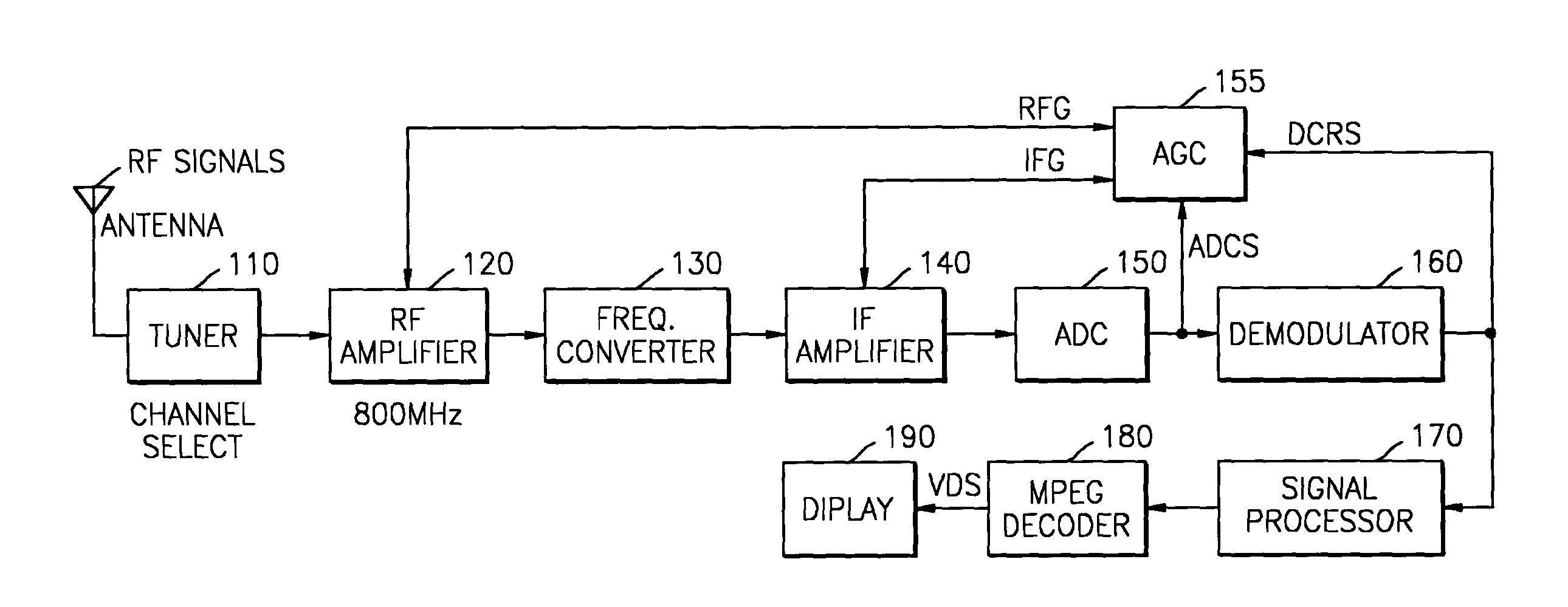
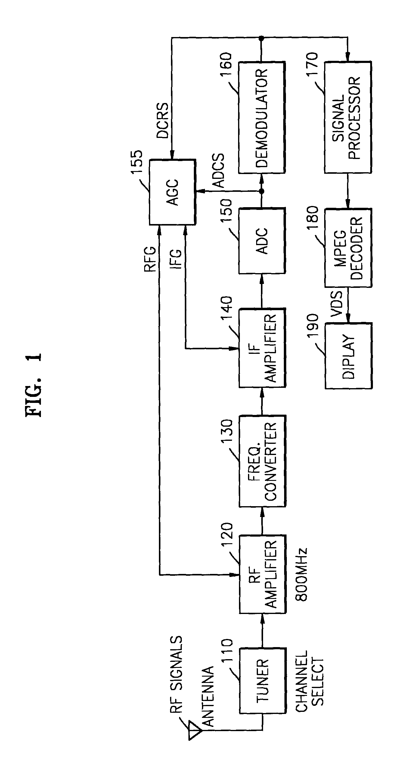
[0028]According to preferred embodiments of the present invention, a digital television receiver and method are provided for acquiring spurious signals and signal oscillations, monitoring outputs of a matched filter of a demodulator, and independently controlling IF / RF gains, using multi-step gear conversion having a hysteresis characteristic.

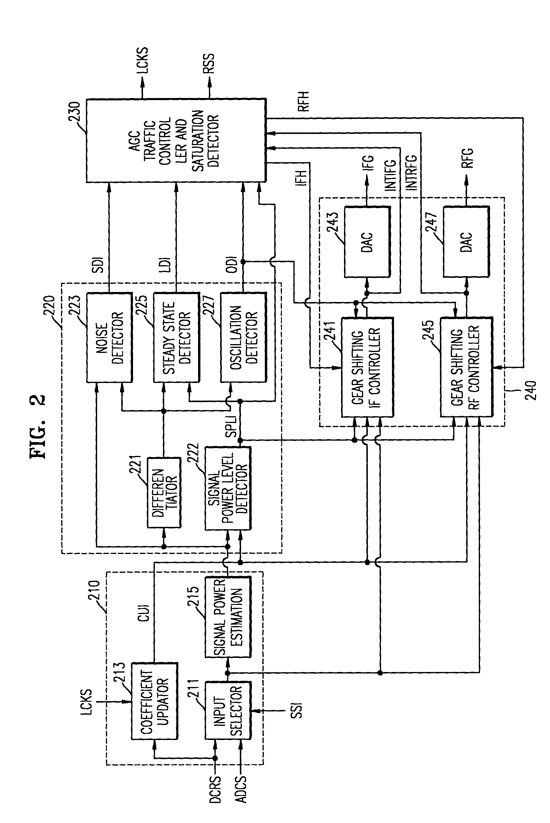
[0029]According to one embodiment of the invention, a signal estimation unit receives a VSB digital signal ADCS, and a demodulated signal of the VSB digital signal, selects and outputs one among the VSB digital signal and the demodulated signal, corresponding to signal selection information, measures and outputs a power value of the selected signal, and outputs coefficient update information if locking information is activated, wherein the coefficient update information is modified according to a saturation state level of the demodulated signal.

[0030]A signal state detection unit calculates signal characteristic information including a temporal...


PUM


Abstract

An automatic gain controller (AGC) and method for use in a digital TV receiver having an IF amplifier, an RF amplifier, an analog to digital converter (ADC) connected to the IF amplifier, and a demodulator connected to the ADC, the AGC comprising: an input selector for selecting as feedback signal one of a digitized IF signal output of the ADC and a demodulated signal output of the demodulator; a signal detection unit for detecting the conditions of the feedback signal and outputting status signals; and a traffic controller for receiving the status signals and outputting control signals based on the status signals to an IF gain controller and an RF gain controller for independent gain control of the RF amplifier and the IF amplifier. The AGC and method further including hysteresis-curve-based switching for alternatively halting adjustments to IF gain while adjusting RF gain or halting adjustments to RF gain while adjusting IF gain.

Description

BACKGROUND OF THE INVENTION[0001]This application claims priority to Korean Patent Application No. 2003-24341, filed on Apr. 17, 2003, in the Korean Intellectual Property Office.[0002]1. Field of the Invention[0003]The present invention relates to digital television (hereinafter, referred to as “DTV”), and more particularly, to an automatic gain controller (AGC) of a digital television (DTV) receiving unit.[0004]2. Discussion of the Related Art[0005]Digital television broadcasts produce higher definition or higher resolution television (HDTV) as compared to traditional analog TV broadcasts. The pictures reproduced from a HDTV broadcast are higher resolution and are less grainy. The images reproduced appear more livelier. DTV signal broadcast formats are defined by the Advanced Television Systems Committee (ATSC). Broadcast signals include vestigial sideband (“VSB”), e.g. 8-VSB for the United States. It is known that broadcasts of VSB signals are susceptible to multipath interference...

Claims


Application Information

Patent Timeline
Patent Type & Authority Patents(United States)
IPC IPC(8): H04N5/44H04B7/00H03G3/30H04N5/52
CPCH03G3/3068H04N21/44209H04N5/52H04N5/4401H04N21/426
Inventor PAIK, WON-KYUKIM, DO-HAN
Owner SAMSUNG ELECTRONICS CO LTD
Learn More