Wireless communication system and receiving device

a communication system and receiving device technology, applied in multiplex communication, pulse technique, instruments, etc., can solve the problems of increasing power consumption, expanding the circuit scale, costing, etc., and achieve excellent error rate performan

Inactive Publication Date: 2007-09-18
FUJITSU LTD
View PDF10 Cites 80 Cited by
  • Summary
  • Abstract
  • Description
  • Claims
  • Application Information

AI Technical Summary

Benefits of technology

[0012]It is an object of the present invention to provide a wireless communication system and a receiving device that are capable of restraining the circuit scale and acquiring an excellent error rate performance.
[0016]Thus, the present invention actualizes eigenmode transmission by using, as the precoding matrix, a partial matrix of a right singular matrix obtained by singular value decomposition (SVD) of the channel matrix. Then, in this type of eigenmode transmission, the signal-to-noise ratio is obtained from the channel matrix estimated in the receiving device, and the path metric is weighted by the signal-to-noise ratio using as the weighting coefficient, thereby improving an error rate performance of the Viterbi decoding.
[0018]With this scheme, according to the present invention, also in such a configuration that the number of transmission data streams is equalized to the number of the plurality of transmitting antennas and the transmitting device performs neither adaptive modulation nor power control, an excellent error rate performance can be acquired by the simple signal process in the receiving device. Then, the present invention does not require any circuit components related to the adaptive modulation, the power control etc, and hence a circuit scale of the device itself can be restrained.
[0022]Therefore, according to the present invention, a combination of the frequency interleaving and the weighted Viterbi algorithm enables the error rate performance to be improved by the simple signal processing in the receiving device.
[0024]From the feature of the channel eigenmode described above, the channel eigenvalues have the proportional relationship with the thus-calculated signal-to-noise ratio, and it is therefore possible to obtain the same effect as in the case of using the channel eigenvalues as the weighting coefficient.
[0029]According to the present invention, it is feasible to provide the wireless communication system and the receiving device each capable of restraining a circuit scale and obtaining an excellent error rate performance.

Problems solved by technology

In the conventional MIMO-OFDM wireless communication system described above, however, if the number of transmitting / receiving antennas increases while actualizing the adaptive modulation and the adaptive transmission power control, circuit configurations of the transmitting device and the receiving device become complicated, a circuit scale expands, and there arise problems such as cost-up and an increase in power consumption.

Method used


Image

  • Wireless communication system and receiving device
  • Wireless communication system and receiving device
  • Wireless communication system and receiving device

Examples


first embodiment

Operation / Effect in First Embodiment

[0083]Herein, operations and effects of the MIMO-OFDM wireless communication system in the first embodiment discussed above will be stated with respect to each of the transmitting device 100 and the receiving device 200.

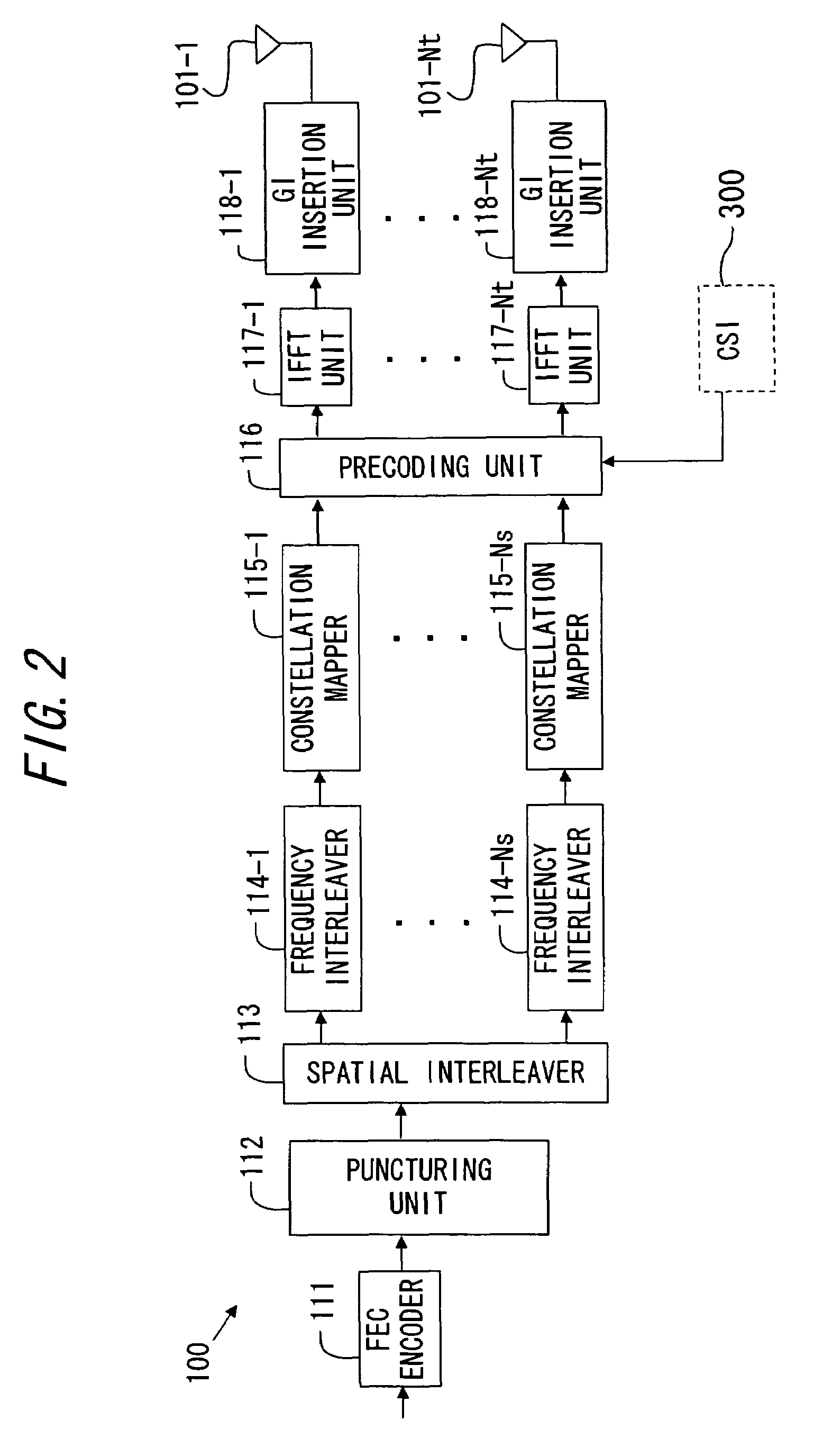
[0084]In the transmitting device 100, the transmission bit sequence is encoded by the FEC encoder 111 in a way that uses the convolutional code etc and is, after being punctured by the puncturing unit 112, split by the spatial interleaver 113 into Ns-pieces of data streams. The thus-split data streams are allocated to the predetermined subcarrier signals by the respective frequency interleavers 114-1 through 114-Ns provided corresponding to the data streams, and are mapped respectively to the subcarrier signals (transmission data streams) by the constellation mappers 115-1 through 115-Ns on the basis of the fixed predetermined constellation.

[0085]Thus, in the first embodiment, the transmission bit sequence is split into the data st...

modified example

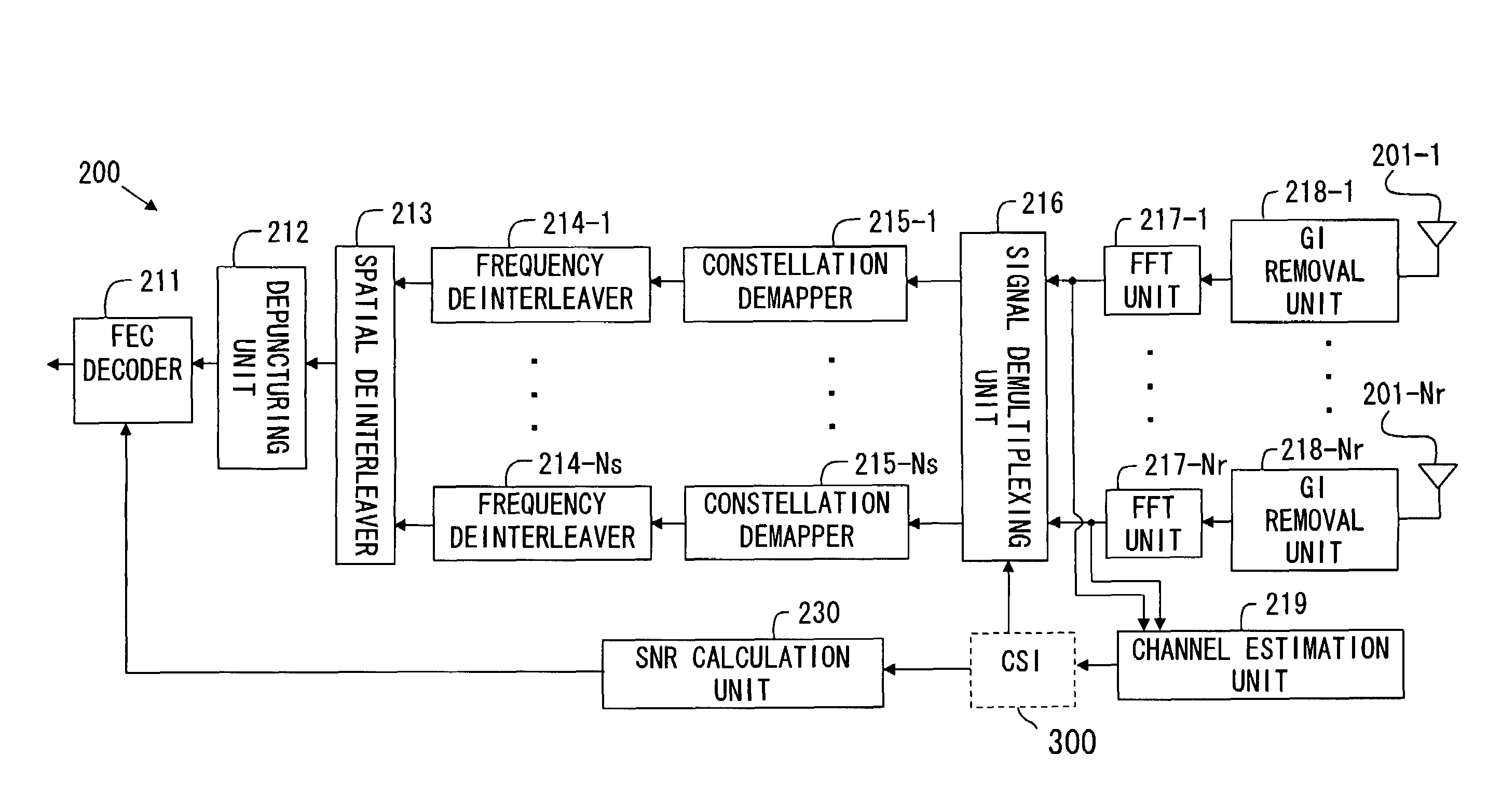
[0098]In the receiving device in the MIMO-OFDM wireless communication system in the first embodiment discussed above, the FEC decoder 211 performs the Viterbi decoding by utilizing, as the weighting coefficient, the channel eigenvalues corresponding to the subcarrier k with respect to the estimation bit sequence received by each subcarrier k, however, in place of this channel eigenvalues, the SNR of the valid channel may also be used as the weighting coefficient.

[0099]FIG. 6 is a diagram showing a circuit configuration in the modified example of the receiving device in the first embodiment. As illustrated in FIG. 6, the receiving device in the modified example includes an SNR calculation unit 230 as a substitute for the eigenvalue processing unit 220 of the receiving device in the first embodiment. The function units other than this unit are the same as those in the first embodiment, and therefore their explanations are omitted.

[0100]The SNR calculation unit 230 sets H(k)×F(k) shown...

second embodiment

[0105]The MIMO-OFDM wireless communication system according to a second embodiment of the present invention will hereinafter be described.

Transmitting Device

[0106]An example of the circuit configuration of the transmitting device 100 in the second embodiment will hereinafter be explained with reference to FIG. 7. FIG. 7 is a block diagram showing an example of the circuit configuration of the transmitting device 100 in the second embodiment.

[0107]The transmitting device 100 in the second embodiment is configured so that the output from the spatial interleaver 113 is, as shown in FIG. 7, inputted to the preceding unit 116, and there are provided other components such as the FEC encoders 111-1 through 111-Nx, the puncturing units 112-1 through 112-Nx, the frequency interleavers 114-1 through 114-Nx and the constellation mappers 115-1 through 115-Nx, of which the numbers each correspond to a parallel process count Nx. Note that this parallel process count Nx may be the same as the numb...


PUM


Abstract

The present invention is to provide a wireless communication system and a receiving device each capable of restraining a circuit scale and obtaining an excellent error rate performance. In a wireless communication system in which a transmitting device and a receiving device communicate in an orthogonal frequency division multiplexing system, the transmitting device includes a partition unit partitioning a transmission data sequence into a plurality of data streams and a mapping unit mapping the plurality of data streams to each of transmitting antennas by using, for a precoding matrix, columns, corresponding to a stream count of the plurality of data streams, of a right singular matrix acquired by singular value decomposition of a channel matrix, and the receiving device includes a decoding unit that Viterbi-decodes the received signals by weighting a path metric by using a weighting coefficient corresponding to a signal-to-noise ratio obtained from the present channel matrix.

Description

BACKGROUND OF THE INVENTION[0001]1. Field of the Invention[0002]The present invention relates to a wireless communication system and a receiving device that utilize MIMO (Multiple Input Multiple Output)-OFDM (Orthogonal Frequency Division Multiplexing).[0003]2. Description of the Related Art[0004]A MIMO (Multi Input and Multi Output) communication system exists as a communication system capable of increasing transmission rates (capacity of transmission) by transmitting the same or different data simultaneously from a plurality of antennas by use of the same frequency band. The MIMO communication system is that transmission data are split into Ns-pieces of different data streams, and the respective transmission data streams are simultaneously transmitted from a plurality (Nt-pieces) of transmitting antennas, and these transmitted signals are multiplexed through a variety of communication paths and thus received by a plurality (Nr-pieces) of receiving antennas.[0005]The MIMO receiving...

Claims


Application Information

Patent Timeline
Patent Type & Authority Patents(United States)
IPC IPC(8): G02B6/00H04J15/00H04L27/00H04J99/00
CPCH04B7/0417H04B7/0626H04L1/0631H04L1/065H04L25/03331
Inventor ZHOU, LIANGNAKAMURA, MICHIHARU
Owner FUJITSU LTD
Why Eureka
Try Eureka