Toner holding apparatus, developing apparatus, and image forming apparatus

a technology of developing unit and holding apparatus, which is applied in the direction of electrographic process apparatus, instruments, optics, etc., can solve the problems of increasing the number of parts and complicated construction

Active Publication Date: 2007-09-18
OKI ELECTRIC IND CO LTD
View PDF4 Cites 17 Cited by
  • Summary
  • Abstract
  • Description
  • Claims
  • Application Information

AI Technical Summary

Benefits of technology

[0007]An object of the invention is to provide a toner cartridge of simple construction that requires a small number of parts.
[0015]The agitating member has a second screw conveyor that causes the toner to move in the second chamber when the agitating member is driven to rotate.
[0016]The toner moving member and the agitating member are coupled through a coupling mechanism that extends through an opening formed in the partition wall. The partition wall has a leakage preventing structure that prevents the toner from leaking between the first chamber and the second chamber.

Problems solved by technology

Driving the toner agitating bar 106 and screw conveyor 143 by separate drive sources makes the construction complicated and results in an increased number of parts.

Method used


Image

  • Toner holding apparatus, developing apparatus, and image forming apparatus
  • Toner holding apparatus, developing apparatus, and image forming apparatus
  • Toner holding apparatus, developing apparatus, and image forming apparatus

Examples


first embodiment

{General Construction}

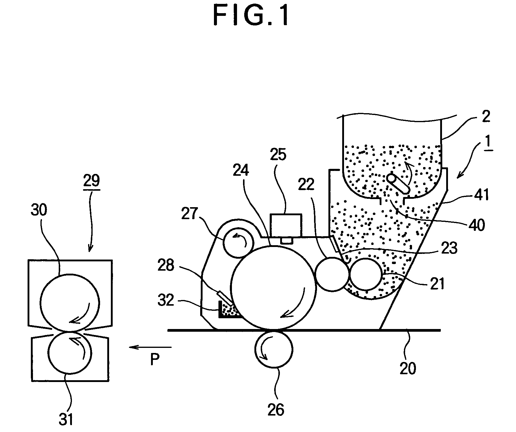
[0041]FIG. 1 is a schematic view of an image forming section of an image forming apparatus such as a printer. A toner cartridge 2 according to a first embodiment is attached to a developing unit 1 and toner is supplied through a toner exit 40. A charging roller 27 is driven by a drive source, not shown, to rotate in contact with a surface of a photoconductive drum 24, thereby charging the surface of the photoconductive drum 24 to a predetermined potential. An exposing unit 25 provided on the body of the printer illuminates the uniformly charged surface of the photoconductive drum 24 to form an electrostatic latent image in accordance with print data.

[0042]A toner cartridge 2 is detachably attached to a developing unit 1. Fresh, unused toner is supplied from the toner cartridge 2 into the developing unit 1. The developing unit 1 is detachably attached to the image forming apparatus. A toner-supplying roller 21 supplies the toner to a developing roller 22 while r...

second embodiment

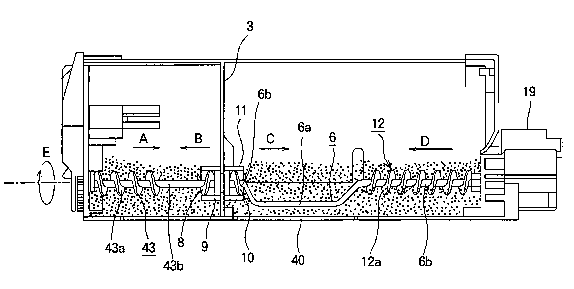
[0060]FIG. 11 illustrates a toner cartridge 2 according to a second embodiment. The second embodiment differs from the first embodiment in that a screw conveyor 43 has a reverse screw conveyor 8.

[0061]The waste toner is received in the waste toner chamber 5 through a waste toner inlet 42, and the screw conveyor 43 moves the waste toner toward the middle of the waste toner chamber 5 while dispersing the waste toner. However, an increase in the amount of waste toner gives rise to a possibility that the waste toner moving in the A direction leaks into the fresh toner chamber 4 through a hole 101 formed in a partition wall 3. In order to prevent the leakage of the waste toner into the fresh toner chamber 4, the toner cartridge according to the second embodiment has the reverse screw conveyor 8 that has a blade 8a that spirals in the opposite direction to the screw conveyor 43. Therefore, when the shaft 43b of the screw conveyor 43 is rotated in a direction shown by arrow E, the screw co...

third embodiment

[0066]FIG. 12 illustrates a toner cartridge according to a third embodiment. The third embodiment further improves the shapes of an agitator bar 6 and a partition wall 3 according to the second embodiment. In other words, an agitator bar 6 has a shaft 6b rotatably supported by a partition wall 3. The agitator 6 has a blade attached to a part of the shaft 6b, the blade describing a spiral about the shaft 6b to form a screw conveyor 10. The partition wall 3 has a hollow cylinder 11 that extends toward the middle portion of the fresh toner chamber 4. The shaft 43b of the screw conveyor 43 and the shaft 6b of the agitator bar 6 are in line with each other and are coupled through the same mechanism as that in FIGS. 8-10. The hollow cylinder 11 has an inner diameter larger than an outer diameter of the screw conveyor 10, so that the hollow cylinder 11 receives the screw conveyor 10 therein and the screw conveyor 10 is rotatable relative to the hollow cylinder 11. The hollow cylinder 11 is...


PUM


Abstract

A toner cartridge includes a first chamber and a second chamber divided by a partition wall. A toner moving member has a screw member that rotates to cause the toner in the first chamber to move. An agitating member includes an agitator bar that agitates the toner in the second chamber. The toner moving member and agitating member are operatively coupled so that one of the toner moving member and the agitating member is driven in rotation, the other of the toner moving member and the agitating member also rotates. The toner moving member is a first screw conveyor. The first screw conveyor spans across substantially half a length of the first chamber.

Description

BACKGROUND OF THE INVENTION[0001]1. Field of the Invention[0002]The present invention generally relates to a toner cartridge, a developing unit, and an image forming apparatus.[0003]2. Description of the Related Art[0004]FIG. 15 is a side cross-sectional view of a waste toner chamber 105 of a conventional toner cartridge 102 for use in an electrophotographic printer. FIG. 16 is a perspective view of a lid mounted to close one end of the toner cartridge 102 that extends in a longitudinal direction. The toner cartridge 102 includes a fresh toner chamber 104 that holds fresh toner therein and a waste toner chamber 105 that holds waste toner therein. The fresh toner chamber 104 and waste toner chamber 105 extend in their longitudinal directions and are divided by a longitudinally extending partition wall. The fresh toner chamber 104 includes an agitating bar 106 for agitating the fresh toner in the fresh toner chamber 104. The agitating bar 106 is connected to a drive gear 107, which is...

Claims


Application Information

Patent Timeline
Patent Type & Authority Patents(United States)
IPC IPC(8): G03G15/08
CPCG03G21/105G03G21/12G03G15/0855G03G15/0865G03G15/0875
Inventor ITO, JUNICHI
Owner OKI ELECTRIC IND CO LTD
Why Eureka
Try Eureka