Multi-sector in-building repeater

a repeater and multi-sector technology, applied in repeater/relay circuit, baseband system details, transmission monitoring, etc., can solve the problems of limited number of repeaters at the far end, difficult transmission of signals to a distant place, and often occurring transmission loss, so as to increase frequency and sector, the effect of maximizing transmission efficiency

Inactive Publication Date: 2007-09-18
SAMSUNG ELECTRONICS CO LTD
View PDF10 Cites 183 Cited by
  • Summary
  • Abstract
  • Description
  • Claims
  • Application Information

AI Technical Summary

Benefits of technology

[0028]It is, therefore, an object of the present invention to provide multi-sector in-building transmission and reception process, and a repeater to maximize transmission efficiency, by increasing frequency and sector.

Problems solved by technology

The high frequency signal is not transmitted directly from the digital unit to the remote access unit, but is first converted into a low frequency wave at the digital unit before transmission, because when high frequency signals are transmitted between the digital unit and the remote access unit via wire, transmission loss often occurs and transmission of signals to a distant place becomes very difficult.
Generally, the number of repeaters at the far-end is limited by the total output power.
Another defect in the approach of extending FAs is that if a building is located in proximity to a public network service, the frequency being used is usually the same, raising the possibility that handover or disconnection will frequently occur.
When using the approach of increasing sectors, on the other hand, the sector structure at a base transceiver station (BTS) is basically more complex than the omni structure, its implementation involves great costs, and transmission loss is likely to happen because of interlayer handover.
Moreover, when an IF repeater is used, it is not simple to merge signals for six sectors. and transmit to each floor because the signal will be the same FA.

Method used


Image

  • Multi-sector in-building repeater
  • Multi-sector in-building repeater
  • Multi-sector in-building repeater

Examples


Embodiment Construction

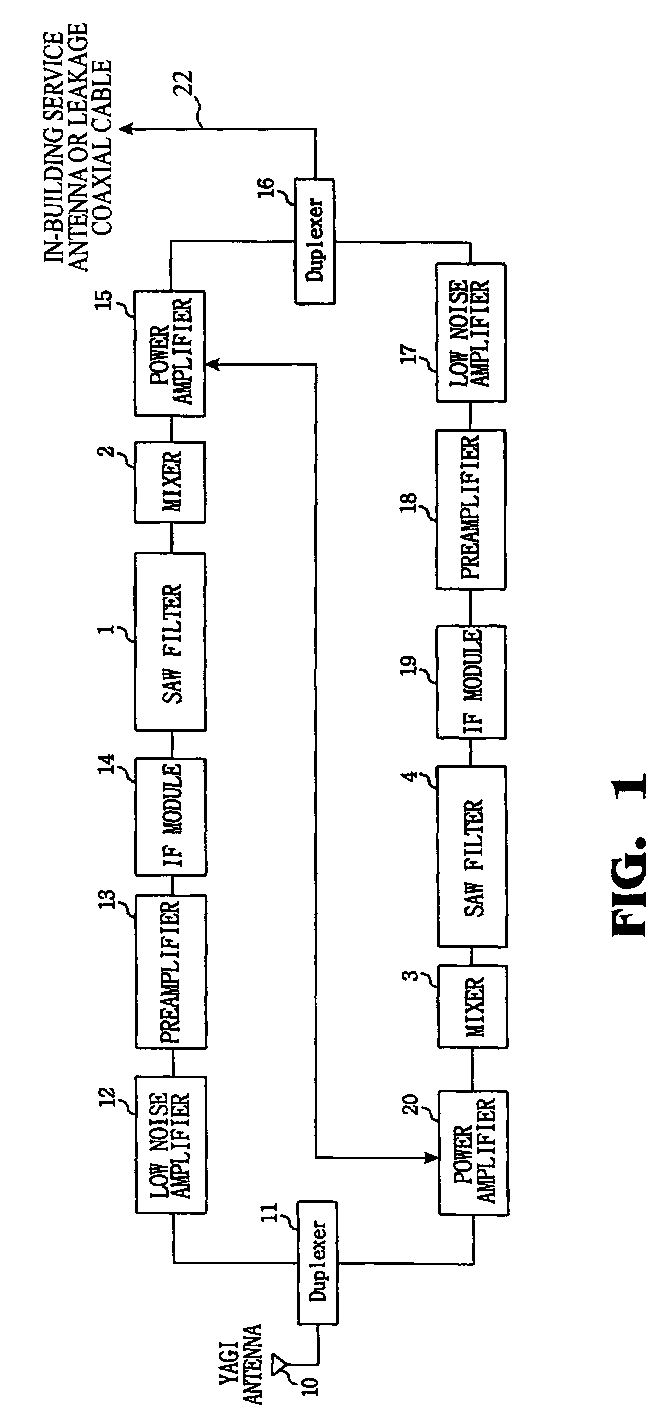
[0049]Turning now to the drawings, FIG. 1 is a structure diagram of an in-building repeater installed in one floor of a building using a CDMA (Code Division Multiple Access) mobile communication system as an example.

[0050]As shown in FIG. 1, the in-building repeater includes duplexers 11 and 16, low noise amplifiers 12 and 17, preamplifiers 13 and 18, intermediate-frequency modules 14 and 19, surface acoustic wave (SAW) filters 1 and 4, mixers 2 and 3, and power amplifier 15.

[0051]Operating principles of the in-building repeater with the above configuration are explained below.

[0052]When a high frequency signal is received from a base station through a Yagi antenna 10, the received signal is transmitted to the low noise amplifier 12 in the transmission direction through the duplexer 11.

[0053]Then, low noise amplifier 12 and preamplifier 13 amplify the signal, and intermediate-frequency (IF) module 14 converts the amplified signal into an intermediate frequency signal.

[0054]Next, SAW...


PUM


Abstract

A multi-sector in-building repeater, including: a master transmitting unit for receiving multi-sector signals of a carrier from a base station, mixing the multi-sector signals with different transmission intermediate frequency signals, and outputting mixed multi-sector signals to a same transmission line; a plurality of slave transmitting units for extracting sector signals assigned to the multi-sector signals from the master transmitting unit, converting extracted sector signals into high frequency signals, and transmitting converted high frequency signals through an antenna to a mobile terminal.

Description

CLAIM OF PRIORITY[0001]This application makes reference to and claims all benefits accruing under 35 U.S.C. § 119 from an application for MULTI-SECTOR IN-BUILDING REPEATER earlier filed in the Korean Intellectual Property Office on the 30th of Jan. 2003 and there duly assigned Serial No. 2003-6149.BACKGROUND OF THE INVENTION[0002]1. Field of the Invention[0003]The present invention relates to an in-building repeater, and more particularly, to a process and a multi-sector in-building repeater, capable of maximizing transmission efficiency of by increasing frequency and sector.[0004]2. Description of the Related Art[0005]A widely spread personal communication system (PCS) is the general term for a next generation of mobile communication with client-centered service, which is intended to overcome defective service by mobile phones in a related art; in other words, PCS should provide an ideal communication service through which a person can talk over the phone with others anytime, anywh...

Claims


Application Information

Patent Timeline
Patent Type & Authority Patents(United States)
IPC IPC(8): H04B1/44H04B7/24H04B7/216H04B7/26H04Q7/36
CPCH04B7/155H04B7/2606
Inventor JEONG, CHANG-RAELEE, GUI-JUNGPARK, TAE-HOON
Owner SAMSUNG ELECTRONICS CO LTD
Why Eureka
Try Eureka