
Safety equipment for building sites

a safety equipment and building site technology, applied in the direction of lifting devices, building scaffolds, domestic objects, etc., can solve problems such as drying out of construction work, and achieve the effect of simple equipment and easy assembly

Inactive Publication Date: 2007-09-25
FUNES GAVILAN TOMAS
View PDF14 Cites 13 Cited by
  • Summary
  • Abstract
  • Description
  • Claims
  • Application Information

AI Technical Summary

Benefits of technology

[0012]On the other hand, the side area on at least one of these pieces of equipment has the means to rapidly connect a fence using the transverse mechanism to join it to the safety posts. This fencing or rail offers the required safety to guarantee protection around the outside of the building site as well as providing access to interior stairways for instance, lift shafts and flat roofs. The layout of the banister as overall protection equipment prevents potentially fatal falls. In order to achieve this, the aforementioned banister as part of the safety equipment is designed to withstand weight and impact from the employees and building equipment present on the site.
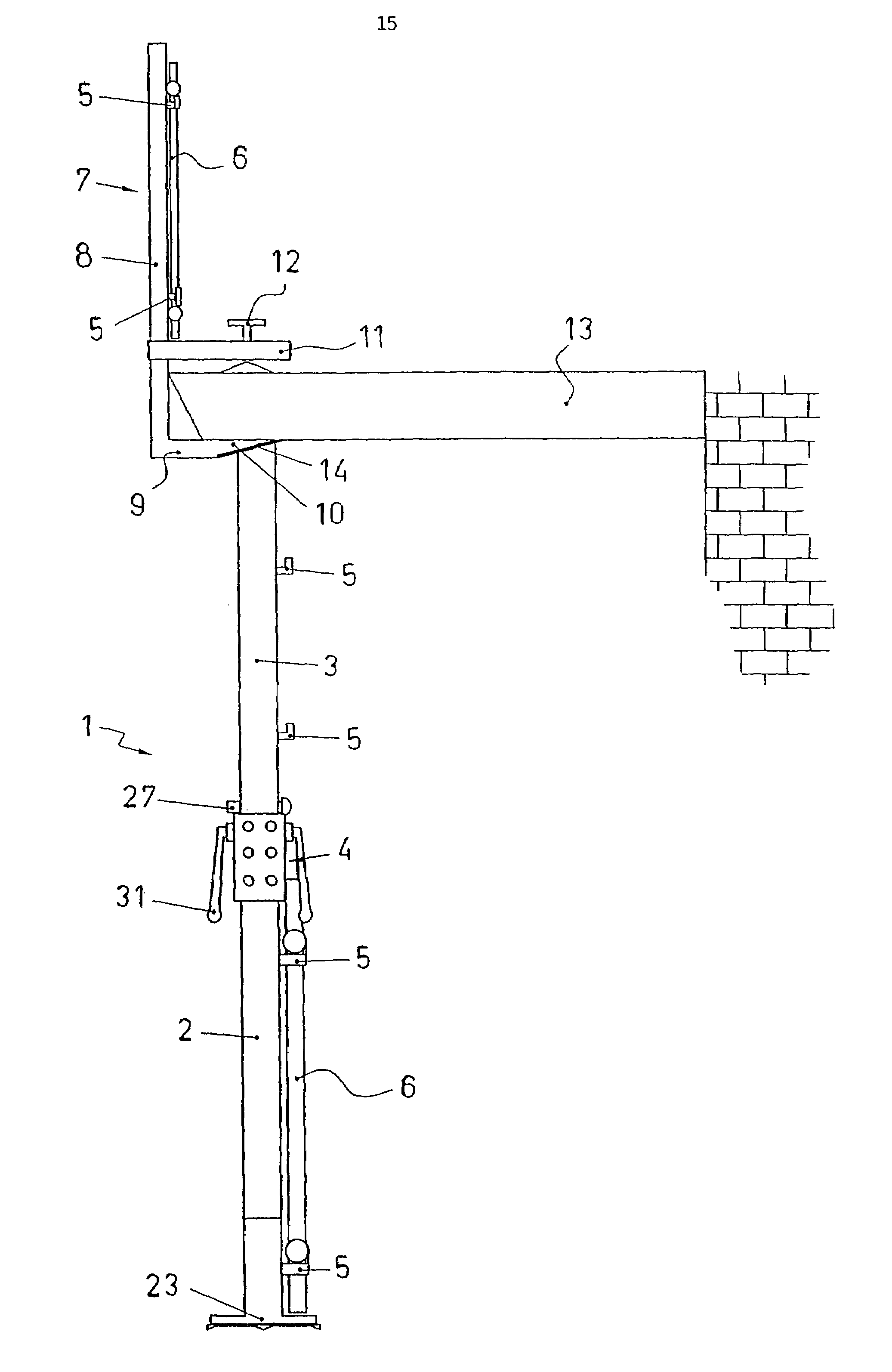
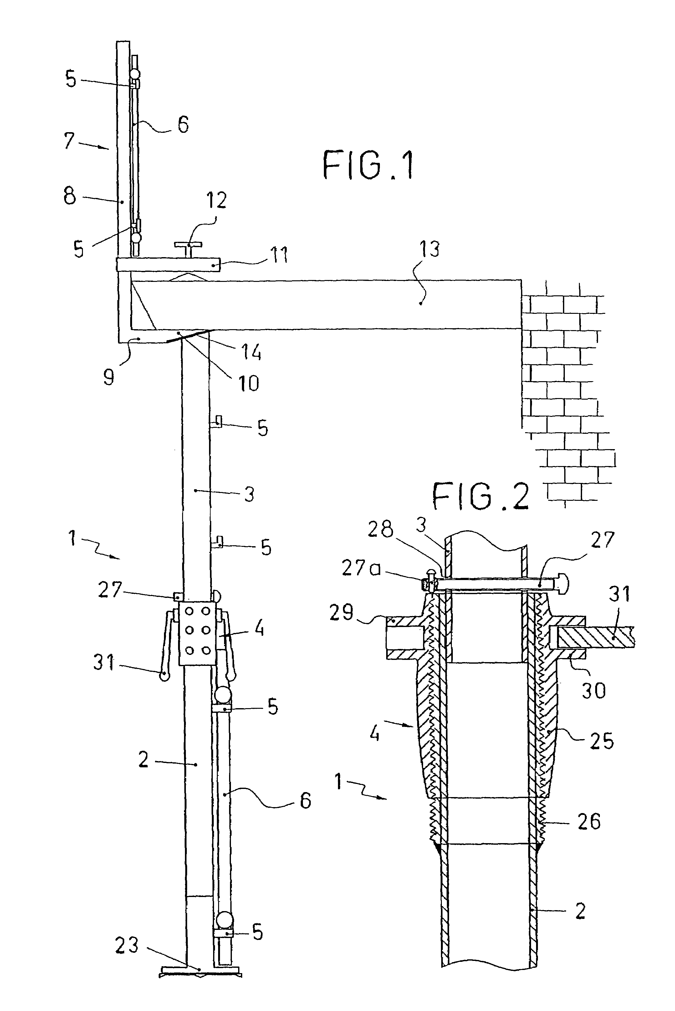
[0014]As an option, the invention may be equipped with an upper safety part which is especially adapted to connect a safety fence in such areas as a house's balcony or similar locations where there are no safety posts. This upper safety part comprises a vertical holding piece with the lower end having a horizontal extension ending in an inclined plane. The aforementioned upper holding piece on the safety equipment includes a horizontal part which moves vertically along it and is equipped with a locking mechanism. The configuration of this vertical holding piece lets a cornice or a protuberance on a building to be captured between the aforementioned horizontal extension and the moveable horizontal part as though it were a chuck. By doing this, the aforementioned inclined plane is properly supported on the upper end of the safety post. Therefore, the vertical holding piece remains fixed throughout the building work. The aforementioned inclined plane, which is in the shape of a disc, may include a rubber safety base between it and the end of the safety post which it can rest on to prevent any of the parts from moving as happens with the aforementioned safety post. The vertical holding piece has rapid connection parts like the transversal fencing in accordance with the other parts of the invention. These connections allow fencing to be located in higher areas of the building work, above the safety posts, on balconies for example. Therefore the invention can become very simply constructed, highly effective dual safety equipment.
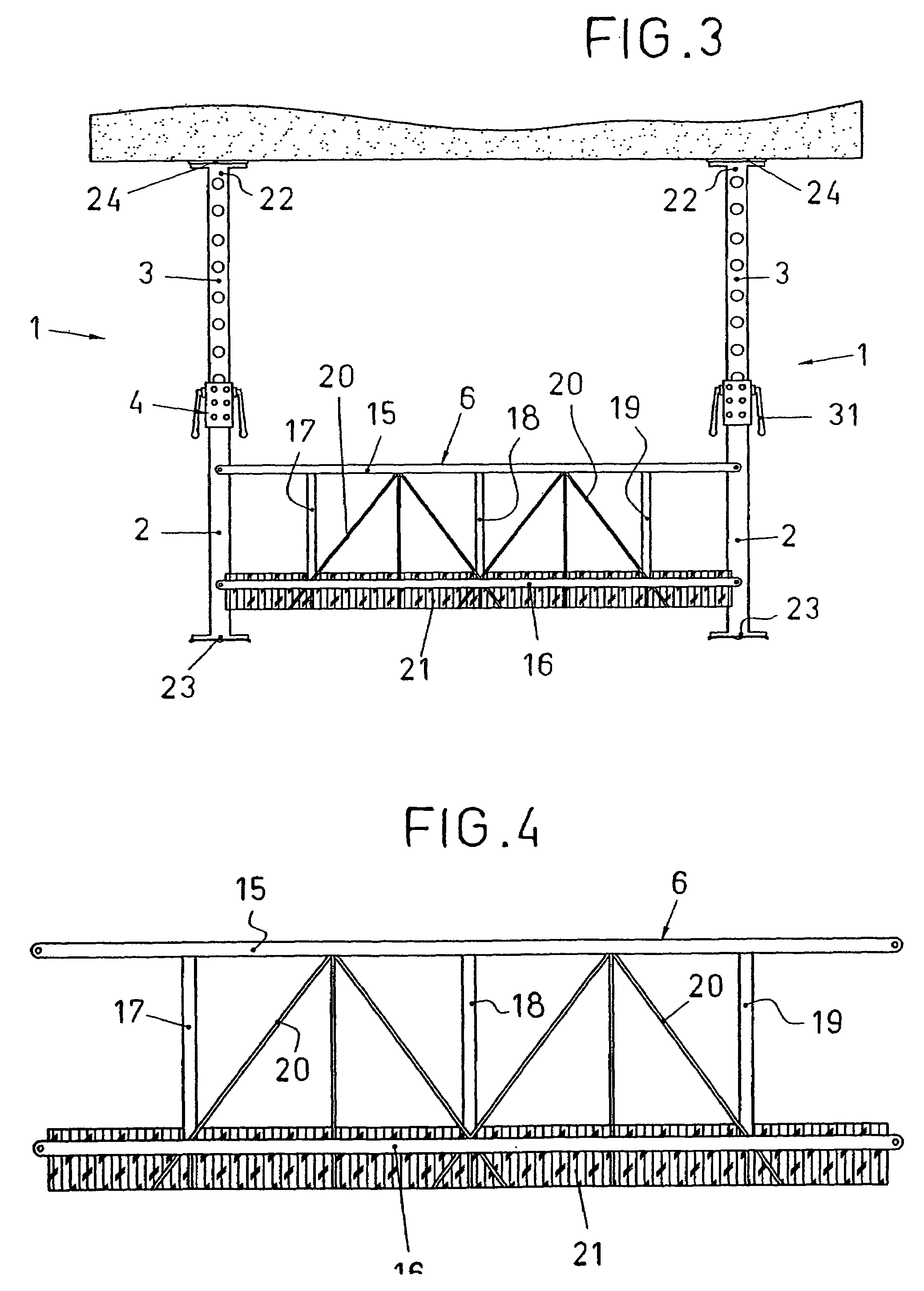
[0015]The way the equipment has been invented means that the safety fencing includes a base or kick plate covering its lower section. The kick plate is designed to stop objects from falling onto people on the building site or to prevent an employee getting past it and removing the base to get inside the fencing. It is therefore, a part which reinforces the safety equipment's safety.
[0018]In order to simplify the equipment and to make it easy to assemble, the rapid connection devices on the aforementioned fencing are made from hooks designed to be located in the openings on the fencing. A specific example of this would mean that these rapid fencing connection devices are pairs of hooks on the side of each safety post tube which are designed to be put into the respective pairs of holes on the fences forming them into a right angle. Here, each hook in the pairs of hooks is welded to the safety post at different heights to prevent interference between the aforementioned fencing.
[0019]The rapid fencing connection devices on the invention are on every tube on each safety post so that the safety post may connect fencing at different heights. This guarantees safety on the building site in any situation and for any type of work being carried out.

Problems solved by technology

However, safety posts in this invention are designed to support side impacts and not to avoid slide sideways when receiving impacts, vibrations and the possibility cracks in the construction work drying out.

Method used


Image

  • Safety equipment for building sites
  • Safety equipment for building sites
  • Safety equipment for building sites

Examples


Embodiment Construction

[0026]The parts used in the preferred configuration of the invention are described below:[0027](1) Safety post;[0028](2) Lower tube;[0029](3) Upper tube;[0030](4) Safety post locking mechanism;[0031](5) Fencing rapid connection mechanism;[0032](6) Fencing;[0033](7) Upper safety piece;[0034](8) Vertical holding piece;[0035](9) Horizontal extension;[0036](10) Inclined plane disc;[0037](11) Vertically moving horizontal piece;[0038](12) Moveable horizontal piece locking mechanism;[0039](13) Building cornice or protuberance;[0040](14) Rubber safety base;[0041](15, 16) Horizontal fencing bars;[0042](17, 18, 19) vertical fencing bars;[0043](20) Reinforcing fencing bars;[0044](21) Kick plate;[0045](22, 23) Safety post tube ends;[0046](24) Non-slip safety post piece;[0047](25) Safety post locking tube mechanism;[0048](26) External thread on the upper end of the lower safety post tube;[0049](27) Rod;[0050](27a) Rod safety lock;[0051](28) Upper tube openings;[0052](29, 30) Side openings on saf...


PUM


Abstract

The invention relates to a construction safety assembly. The inventive assembly comprises: safety posts with non-skid ends, which are provided with means for the rapid connection of a barrier; and, optionally, an upper jack-type safety element having a lower horizontal protrusion along an inclined plane, which is used to brace the cornice or projecting element of a building and which can also comprise the aforementioned barrier connection means. The adjustable-length barrier comprises a base which covers the lower part thereof. In this way, the invention provides a dual safety assembly of very simple construction, which can be used to guarantee the collective safety of labourers performing external and internal construction work and prevent accidents.

Description

CROSS REFERENCE TO RELATED APPLICATION[0001]The present application is a 35 U.S.C. §§ 371 national phase conversion of PCT / ES2004 / 000080, filed 24 Feb. 2004, which claims priority of Spanish Application No. R200300462, filed 26 Feb. 2003. The PCT International Application was published in the Spanish language.BACKGROUND OF THE INVENTION[0002]This is formed by safety posts with non slip ends which are equipped with rapid connection parts for fencing and with the option of an upper safety part in the form of a jack with a lower, horizontal, inclined extension to be attached to a building's cornice or protuberance which may also include these fencing connection methods. They may be extended in length and include a base which covers the lower part of the same.[0003]It's very simple construction means that it is possible to guarantee the overall protection of workers on outdoor and indoor building sites, preventing accidents with the invention's safety equipment.[0004]This appplication f...

Claims


Application Information

Patent Timeline
IPC IPC(8): A47F5/00E04G21/32E04G25/06
CPCE04G21/3233E04G25/06Y10S256/06E04G25/061E04G25/065E04H17/18E04G21/32
Inventor FUNES GAVILAN, TOMAS
Owner FUNES GAVILAN TOMAS
Learn More