Spring modulation with fast load-transient response for a voltage regulator

a voltage regulator and spring technology, applied in the field of voltage regulators, can solve the problems of poor conversion efficiency and high cost, and achieve the effects of improving voltage regulator efficiency, fast load-transient response, and reducing the cost of the resul

Inactive Publication Date: 2007-09-25
RICHTEK TECH
View PDF9 Cites 9 Cited by
  • Summary
  • Abstract
  • Description
  • Claims
  • Application Information

AI Technical Summary

Benefits of technology

[0008]By using the spring modulation according to the present invention for modulating the on-time duty-cycle of a voltage regulator, fast load-transient response is achieved, the output capacitors and thereby the cost therefor could be decreased, the output voltage of the voltage regulator will not overshoot even the load-transient response is fast, and the efficiency of the voltage regulator increases.

Problems solved by technology

Therefore, the system becomes not stable, and the output capacitor COUT is required to have larger capacitance, resulting in higher cost and poor conversion efficiency.

Method used


Image

  • Spring modulation with fast load-transient response for a voltage regulator
  • Spring modulation with fast load-transient response for a voltage regulator
  • Spring modulation with fast load-transient response for a voltage regulator

Examples


Embodiment Construction

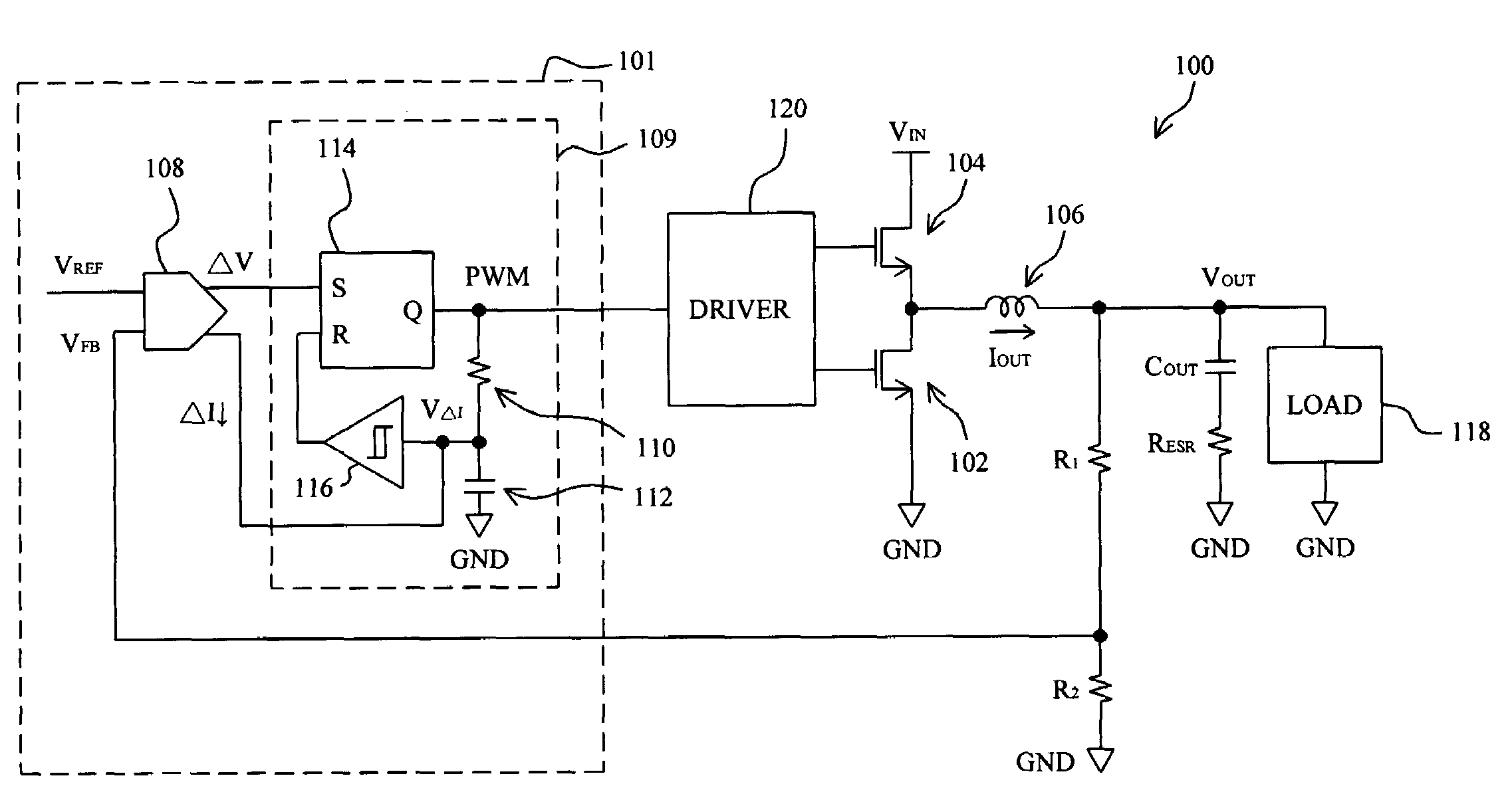
[0016]FIG. 3 shows a voltage regulator 100 employing a spring modulation according to the present invention. In the voltage regulator 100, low side MOS transistor 102 and high side MOS transistor 104 are coupled in series between input voltage VIN and ground GND, spring modulation circuit 101 switches the MOS transistors 102 and 104 with driver 120 to produce output current IOUT flowing through inductor 106 to charge output capacitor COUT to produce output voltage VOUT supplied to load 118, the output capacitor COUT has an equivalent series resistance RESR, resistors R1 and R2 are coupled in series between the output VOUT and ground GND to divide the output voltage VOUT to produce feedback signal VFB, differential amplifier 108 generates differential voltage ΔV and differential current ΔI from the difference between the feedback signal VFB and reference signal VREF, the differential voltage ΔV is coupled to the set input S of RS latch 114 in PWM generator 109, the differential curre...


PUM


Abstract

A spring modulation is proposed to regulate the output voltage of a voltage regulator. The spring modulation comprises a differential amplifier to generate a pair of voltage signal and current signal varied with the difference between a reference signal and a feedback signal related to the output voltage, and a PWM generator to generate a PWM signal in response to the pair of voltage signal and current signal to regulate the output voltage, in such a manner that, in load transient, the greater the difference between the feedback signal and reference signal is, the greater the on-time duty-cycle of the PWM signal is.

Description

FIELD OF THE INVENTION[0001]The present invention is related generally to a voltage regulator and more particularly to a spring modulation for a voltage regulator.BACKGROUND OF THE INVENTION[0002]Voltage regulator has been applied in various electronic products to provide stable supply voltages for load on the voltage regulator. FIG. 1 schematically shows a typical voltage regulator 10 operated with constant on-time duty-cycle, which comprises a pair of high side MOS transistor 12 and low side MOS transistor 14 coupled between input voltage VIN and ground GND, inductor 18 coupled between the phase node 16 between the MOS transistors 12 and 14 and output VOUT of the voltage regulator 10, output capacitor COUT coupled between the output VOUT and ground GND and having equivalent series resistance (ESR) RESR, resistors R1 and R2 coupled in series between the output VOUT and ground GND to divide the output voltage VOUT to generate feedback signal VFB, error amplifier 20 to compare the fe...

Claims


Application Information

Patent Timeline
Patent Type & Authority Patents(United States)
IPC IPC(8): G05F1/565G05F1/575
CPCH02M3/158
Inventor HUANG, KENT
Owner RICHTEK TECH
Why Eureka
Try Eureka