Integrated fuser unit and drive system for use in an electrophotographic imaging process

a technology of fuser unit and drive system, which is applied in the direction of electrographic process equipment, optics, instruments, etc., can solve the problems of reducing the life of gears, reducing the service life of gears, so as to improve the service life and improve the gear center distance control. , the effect of minimizing tolerance variations

Active Publication Date: 2007-09-25
LEXMARK INT INC
View PDF79 Cites 11 Cited by
  • Summary
  • Abstract
  • Description
  • Claims
  • Application Information

AI Technical Summary

Benefits of technology

[0014]An advantage of the present invention is providing improved gear center distance control for all gears in the fuser drive train, thereby minimizing tolerance variations between gear centers, improving gear life and reducing noise.
[0015]Another advantage is providing improved machine reliability by replacing the motor and all drive components each time the fuser unit is replaced.
[0016]A further advantage of the present invention is using the fuser motor to drive the machine output rolls in a reverse direction to feed media into a duplexing path, thereby eliminating the need for an additional duplexer drive motor.
[0017]A still further advantage of the present invention is disconnecting the fuser nip rolls from the drive system as the media is routed to a duplex path, thereby reducing the power needed from the motor, and enabling the motor to turn faster and reduce dead time from duplex routing.
[0018]Yet another advantage of the present invention is changing the direction of drive train rotation without disengaging the drive motor, providing a substantially instantaneous reversal.
[0019]Still another advantage of the present invention is reducing manufacturing cost by minimizing mounting hardware in the base machine frame.

Problems solved by technology

This making and breaking of the drive train creates design challenges and potential problems such as sub-optimal gear center distance control, which can lead to premature gear wear and noise.
Gear life can be shortened and objectionable noise created if the mating gears on the machine side and the fuser unit side are not optimally positioned.
Optimal gear engagement might not result, and increased noise and wear may occur immediately when the new fuser unit is installed.

Method used


Image

  • Integrated fuser unit and drive system for use in an electrophotographic imaging process
  • Integrated fuser unit and drive system for use in an electrophotographic imaging process
  • Integrated fuser unit and drive system for use in an electrophotographic imaging process

Examples


Embodiment Construction

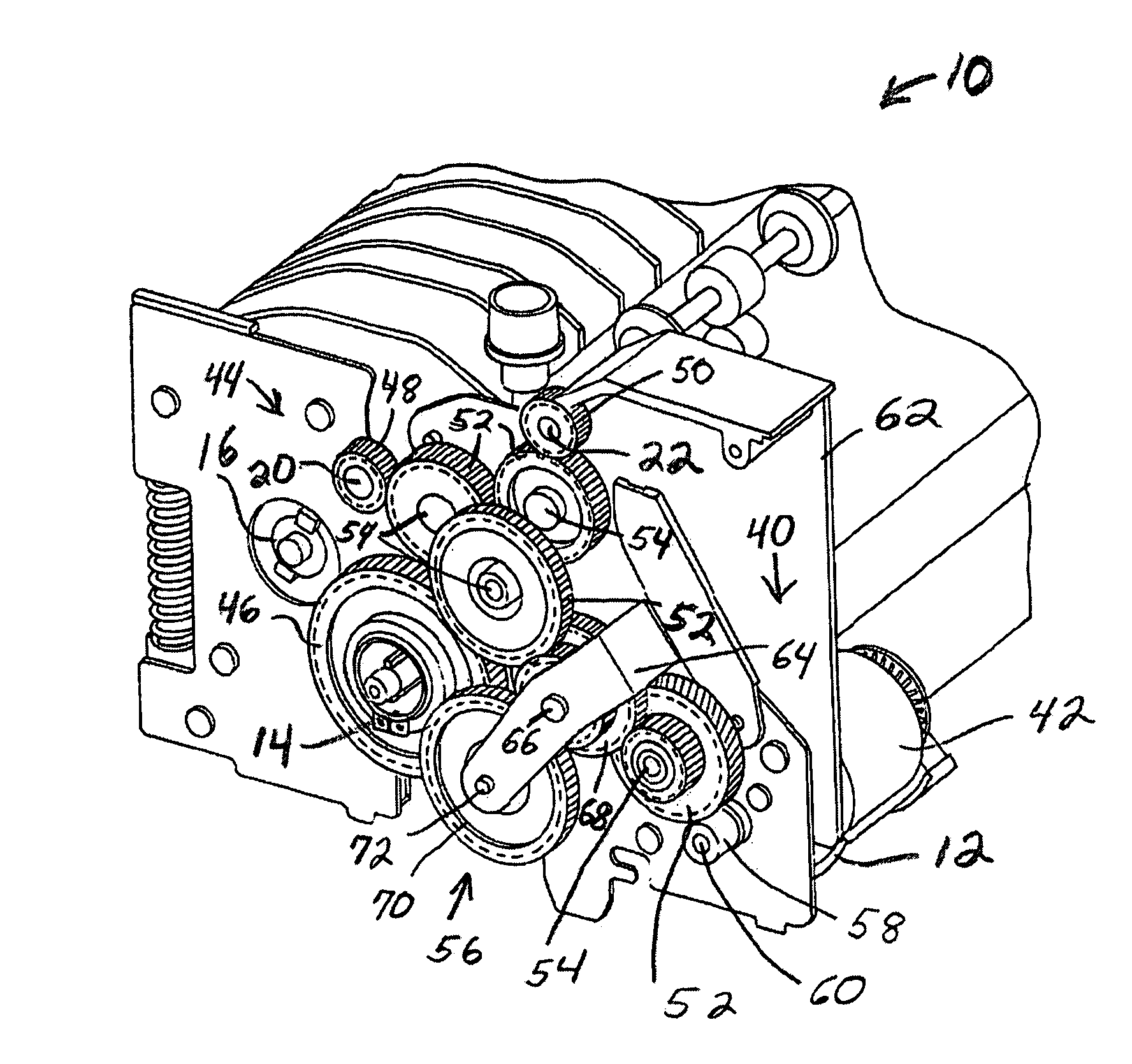
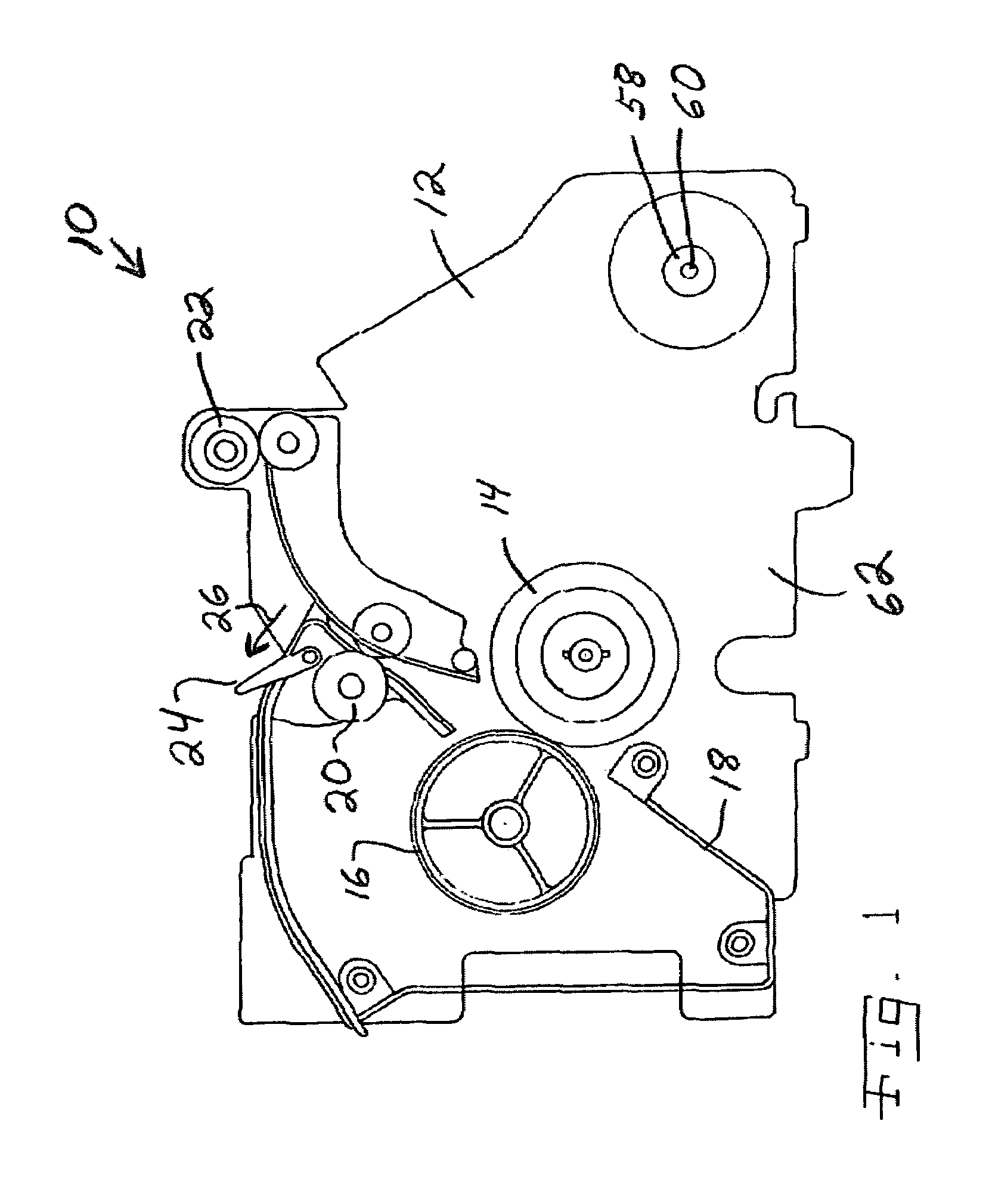
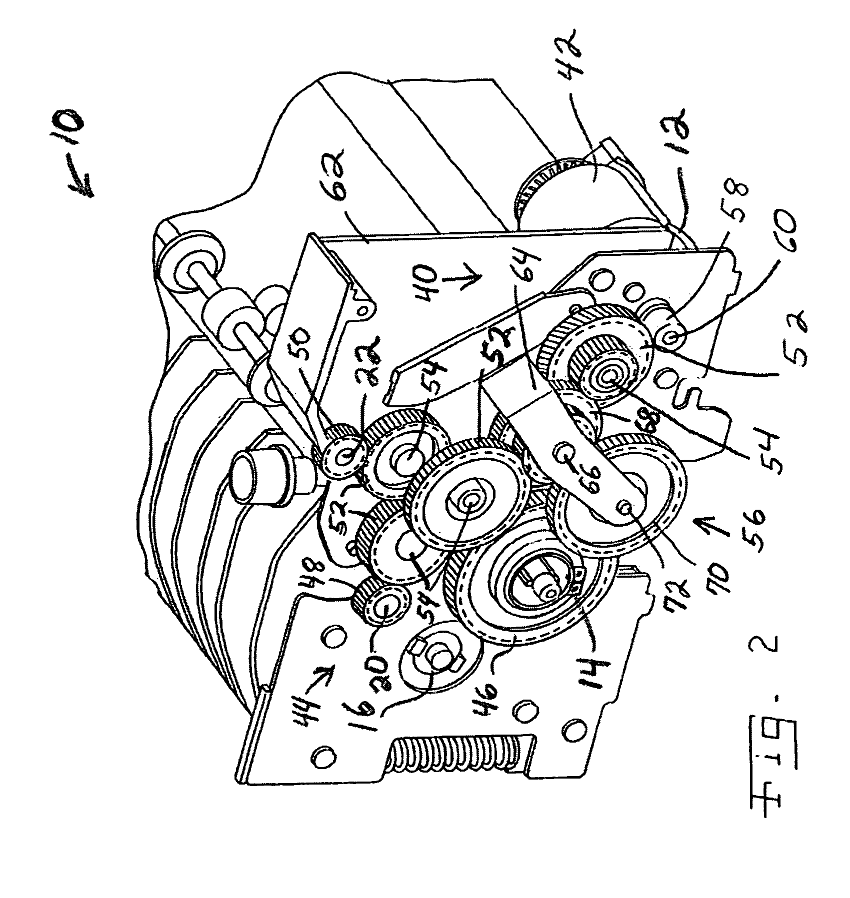
[0025]Referring now to the drawings and particularly to FIG. 1, there is shown an embodiment of a fuser unit 10 for an electrophotographic (EP) printing device in accordance with the present invention. Fuser unit 10 can be adapted for use in a printer, copier or other printing device using the electrophotographic process requiring a fuser unit to permanently adhere toner particles to the media being printed. Fuser unit 10 can be provided for use in a color printing device or a monochrome printing device.

[0026]Fuser unit 10 includes a frame 12 consisting of a variety of substantially ridged members such as plates, bars and the like securely affixed to one another to form a substantially ridged supporting structure for the remaining components of fuser 10. Frame 12 is adapted for mounting in the printing device, and may be provided as a customer replaceable unit (CRU), or a field replaceable unit (FRU). While the features of the present invention also can be used in a fuser integrated...


PUM


Abstract

An integrated fuser unit has a drive system with a motor and a drive train mounted in the fuser unit frame. A swing arm assembly engages and disengages the hot roll from the drive train.

Description

BACKGROUND OF THE INVENTION[0001]1. Field of the Invention[0002]The present invention relates generally to electrophotographic printing devices and, more particularly, to drive systems for the fuser units of electrophotographic printing devices.[0003]2. Description of the Related Art[0004]In the electrophotographic (EP) imaging process used in printers, copiers and the like, a photosensitive member, such as a photoconductive drum or belt, is uniformly charged over an outer surface. An electrostatic latent image is formed by selectively exposing the uniformly charged surface of the photosensitive member. Toner particles are applied to the electrostatic latent image, and thereafter the toner image is transferred to the media intended to receive the final permanent image. The toner image is fixed to the media by the application of heat and pressure in a fuser.[0005]A fuser is known to include a heated roll and a backup roll forming a fuser nip through which the media passes. At least o...

Claims


Application Information

Patent Timeline
Patent Type & Authority Patents(United States)
IPC IPC(8): G03G15/20
CPCG03G15/2064G03G2221/1639
Inventor CARTER, DANIEL LEEKIELY, EDWARD LAWRENCERUSH, EDWARD ALAN
Owner LEXMARK INT INC
Why Eureka
Try Eureka