
Method and apparatus for making dry ice

a technology of dry ice and dry ice, which is applied in the direction of carbon compounds, inorganic chemistry, solidification, etc., can solve the problems of inability to meet the needs of dry ice production, etc., to achieve the effect of reducing pressure, preventing bursting thereof, and reducing labor intensity

Inactive Publication Date: 2007-10-02
VENTURA ENTERPRISES
View PDF15 Cites 23 Cited by
  • Summary
  • Abstract
  • Description
  • Claims
  • Application Information

AI Technical Summary

Benefits of technology

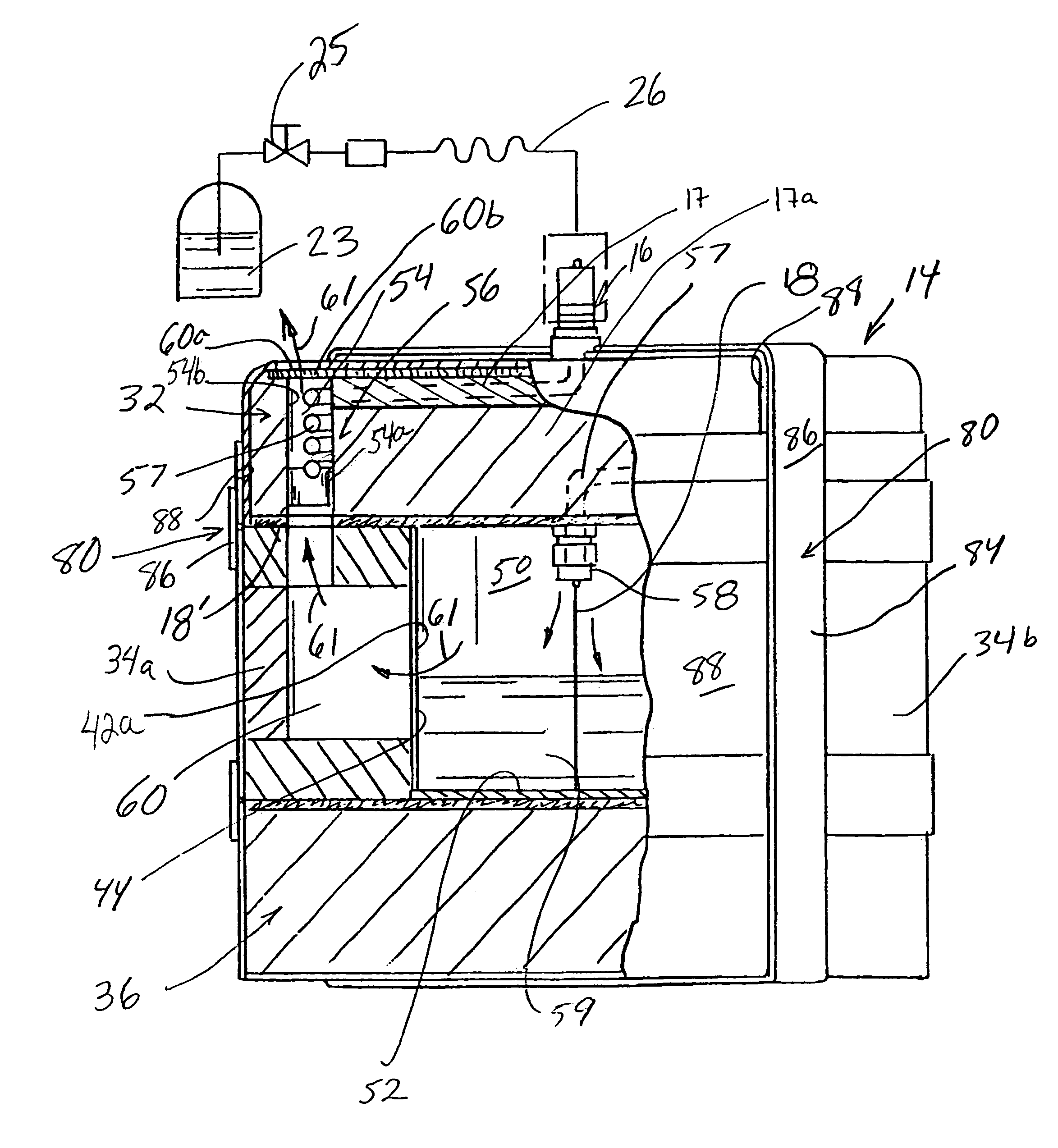
[0021]Still further in accordance with the invention, the apparatus may be configured or constructed to provide a block of solid carbon dioxide without the need for direct manual handling of the block, and / or without the need to remove the block from the apparatus. For example, nearly the entire apparatus may be manufactured of strong, lightweight, low cost materials and may be designed to be disposed of after a single use or shipped to a remote destination along with the dry ice contained there in and, thereafter, optionally returned for re use after the dry ice has been used. Thus, the block of carbon dioxide held in the dry ice chamber does not need to be removed from the apparatus in order to be useful, but advantageously, can be utilized in situ.
[0022]Still further in accordance with the invention, the apparatus may be designed to be efficient and effective in producing a substantially solid, dense mass of solid carbon dioxide.
[0026]Still further in accordance with the invention, the device may include an expansion control assembly designed to permit expansion of the expandable shell assembly during the dry ice making process. Such expansion control assembly may provide an effective means, without the use of conventional pressure relief valves or meters or gauges, for providing an indication to a user that the process of forming dry ice in the dry ice chamber is complete or substantially complete, and the dry ice is ready for use. The expansion control assembly may additionally comprise a fastening member disposed along the at least one self-relieving seam. In a particular embodiment of the invention, the fastening member may cover at least one self-relieving seam. The fastening member may comprise a hook and loop fastening system extending along at least a portion of the at least one self-relieving seam. For example, adjacent shell portions of the expandable shell assembly may include coverings made of a “looped surface” of a Velcro® fastener. Accordingly, the self relieving seam may be covered along at least a portion thereof, with a strip made of a “hooked surface” of a Velcro® fastener. During the dry ice making process the hook and loop fastener maintains the seam in the first (substantially non-venting) position, although there may be some pulling apart of the seam or negligible separation as pressure in the expandable shell assembly increases. Once pressure within the expandable shell assembly increases to a desired level, the hook and loop fastener allows the seam to separate to the second (venting) position, thereby allowing a substantial amount of carbon dioxide gas to escape, usually at a visible level, indicating to a user that the dry ice making process is complete or at least substantially reaching completion. Consequently, the release of this carbon dioxide gas relieves pressure within the dry ice chamber and prevents bursting thereof. The visible carbon dioxide gas at the right moment provides a highly useful, highly reliable indication to a user that the supply of carbon dioxide liquid may be disconnected from the apparatus as the dry ice making process has been completed.

Problems solved by technology

Complex and relatively expensive devices are commercially available for producing large blocks of dry ice which are usually sold in slab or pellet form by commercial ice dealers.
Although there are many practical applications for relatively small quantities of dry ice, for example, keeping foods or small items (e.g. biological specimens) cold for an extended period of time, conventional systems are generally impractical and / or prohibitively expensive for an individual or a small business to use and own.
In addition, due to the extremely cold temperature (−78.5° C., or −109.3° F.) of solid carbon dioxide, manual handling of dry ice exposes the operator to potential injury from physical contact therewith.

Method used


Image

  • Method and apparatus for making dry ice
  • Method and apparatus for making dry ice
  • Method and apparatus for making dry ice

Examples


Embodiment Construction

[0039]Set forth herebelow are detailed descriptions of certain embodiments and examples of the apparatus and methods for making dry ice and products containing and / or encapsulated within dry ice in accordance with the present invention.

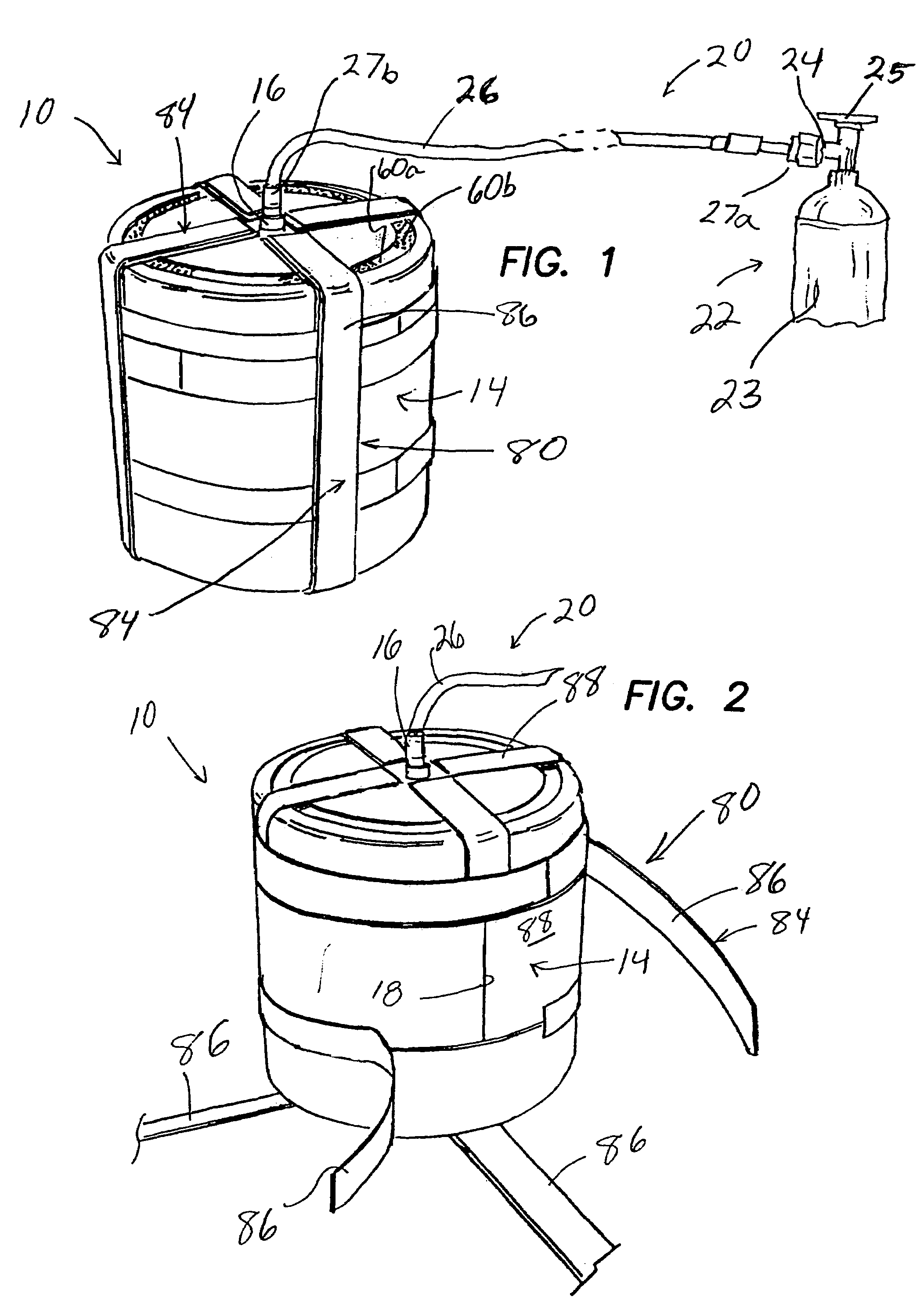
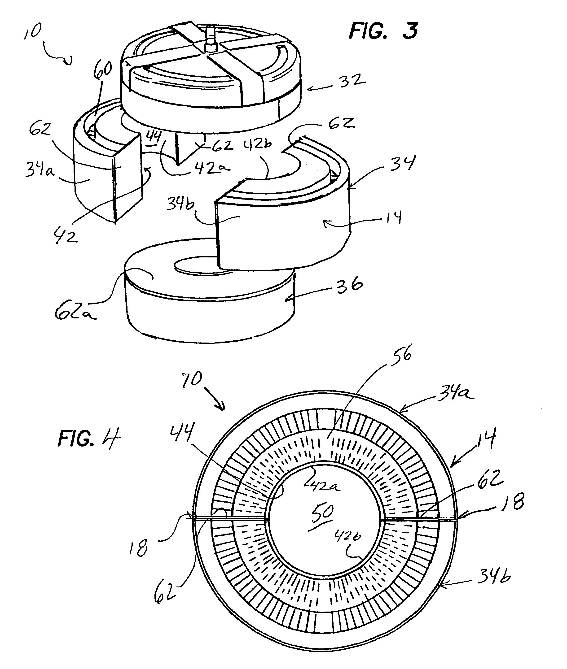
[0040]Turning now to FIGS. 1 and 2, an apparatus 10 in accordance with the present invention is shown, wherein the apparatus 10 generally comprises an expandable shell assembly 14 including an inlet line 16, a dry ice chamber (not shown in FIG. 1) in communication with the inlet line 16, and at least one self-relieving seam 18 (shown in FIG. 2) that is effective to allow expansion of the expandable shell assembly 14 in order to release carbon dioxide gas from the dry ice chamber when the dry ice chamber has been sufficiently filled with solidified carbon dioxide and carbon dioxide gas.

[0041]The apparatus 10 may further comprise a delivery system 20 for delivering liquid carbon dioxide from a source or supply 22 of liquid carbon dioxide to the dry ice ...


PUM


Abstract

An apparatus for producing dry ice is provided. The apparatus generally includes an expandable shell assembly, an expansion control assembly for controlling expansion of the expandable shell assembly, and a delivery system for delivering liquid carbon dioxide from a supply of liquid carbon dioxide to the dry ice chamber. The expandable shell assembly is made of multiple separable shell portions and an inner surface of at least one of the shell portions forms a wall of the dry ice chamber. The expandable shell assembly is structured to automatically relieve pressure within the dry ice chamber when the dry ice chamber has been sufficiently filled with a mass of dry ice.

Description

FIELD OF THE INVENTION[0001]The present invention generally relates to devices and methods for making dry ice and articles containing dry ice, and more specifically relates to devices and methods for making dry ice carbon dioxide which is easily constructed in a convenient size and / or shape using a portable, light weight dry ice machine of the present invention.BACKGROUND OF THE INVENTION[0002]Liquefied carbon dioxide is a cryogenic fluid that is stored in a liquid state under high pressure. When liquefied carbon dioxide is brought into a low pressure environment, such as less than 70 psig, the liquid, through the process of adiabatic expansion, assumes a crystalline form commonly called carbon dioxide snow or dry ice. With time and the absorption of heat, dry ice sublimes to its normal gaseous state. Because the dry ice absorbs large quantities of heat during the sublimation process, it is used in place of ice for cooling substances and / or for keeping a substance in a frozen state....

Claims


Application Information

Patent Timeline
IPC IPC(8): F25J1/00
CPCC01B31/22C01B32/55F25D3/12
Inventor VENTURA, MARK
Owner VENTURA ENTERPRISES
Learn More