Hydrofoil watercraft

a watercraft and foil technology, applied in the field of high-speed watercraft, can solve the problems of serious safety risk for occupants, early designs that failed to overcome the speed limitation of foil-in-water, and the hull was not aerodynamically efficient, so as to reduce electrical noise susceptibility, simplify operation, and ensure stability.

Inactive Publication Date: 2007-10-02
BRASS DWIGHT S
View PDF6 Cites 19 Cited by
  • Summary
  • Abstract
  • Description
  • Claims
  • Application Information

AI Technical Summary

Benefits of technology

[0007]The invention is able to operate in very shallow water due to retractable V-shaped hydrofoil wing. Continuously adjustable V-shaped hydrofoil wing provides maximum lift at partial extension for lower speed transition to hydrofoil mode, especially in shallow water. This design also provides inherent stability due to the inwardly angled lift vectors causing a self-righting operation. Fly-by-fiber controls greatly reduce electrical noise susceptibility and simplify operation. Reversible dual air propellers give simpler, more reliable control of speed, direction, and rotation in-place capability. Independently operable elevators control pitch and roll simply and effectively. All controls remain above water in all modes thus eliminating marine related maintenance and reliability problems. Incorporated strain gages provide feedback to operator for smooth transitions from mode to mode.

Problems solved by technology

These early designs failed to overcome the speed limitation of a foil-in-water due to high drag and cavitation as the foil reached certain speeds.
They were vulnerable to floating debris, especially as speeds increased, posing a serious safety risk for occupants.
In addition, the hull was not aerodynamically efficient further limiting high-speed operation.
Later designs attempted to streamline the hull and incorporated overly complex retractable designs.
Maximum lift is only available when fully extended, which hinders shallow water low speed transition to hydrofoil operation.
This would result in erratic lift and control.
Brubaker's cabin design with a downward sloping nose would pose serious washover problems when in displacement mode (called hullborne by Brubaker).
The Raynes patent uses a float plane design requiring wider wing span and thus limit dockside flexibility as well as the ground-effect advantage.
Still other designs use submerged propellers for propulsion at low speeds limiting shallow water operation and increasing weight and complexity.

Method used


Image

  • Hydrofoil watercraft
  • Hydrofoil watercraft
  • Hydrofoil watercraft

Examples


Embodiment Construction

Cabin

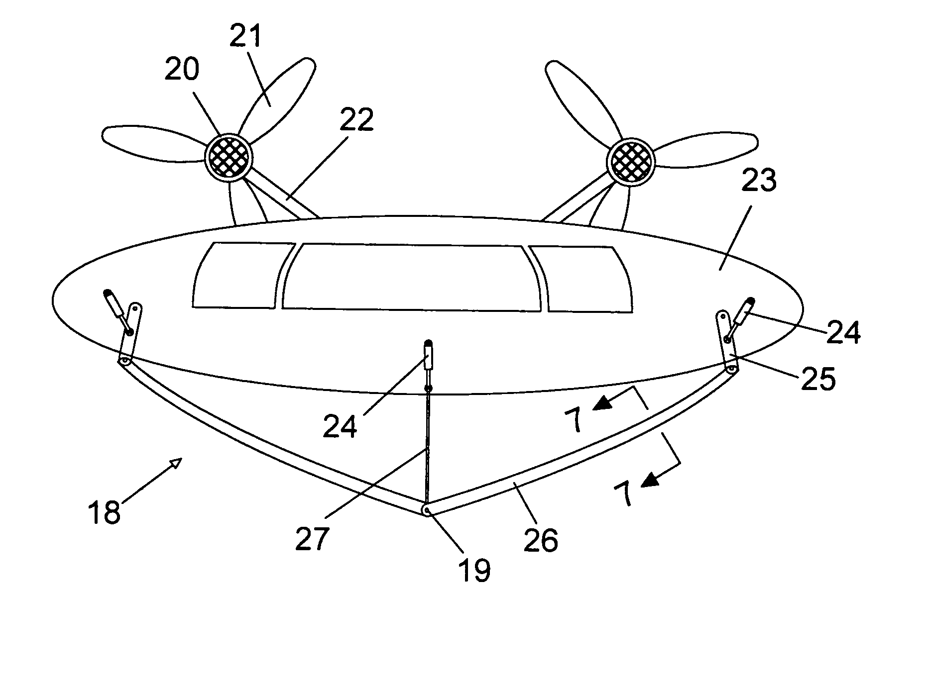
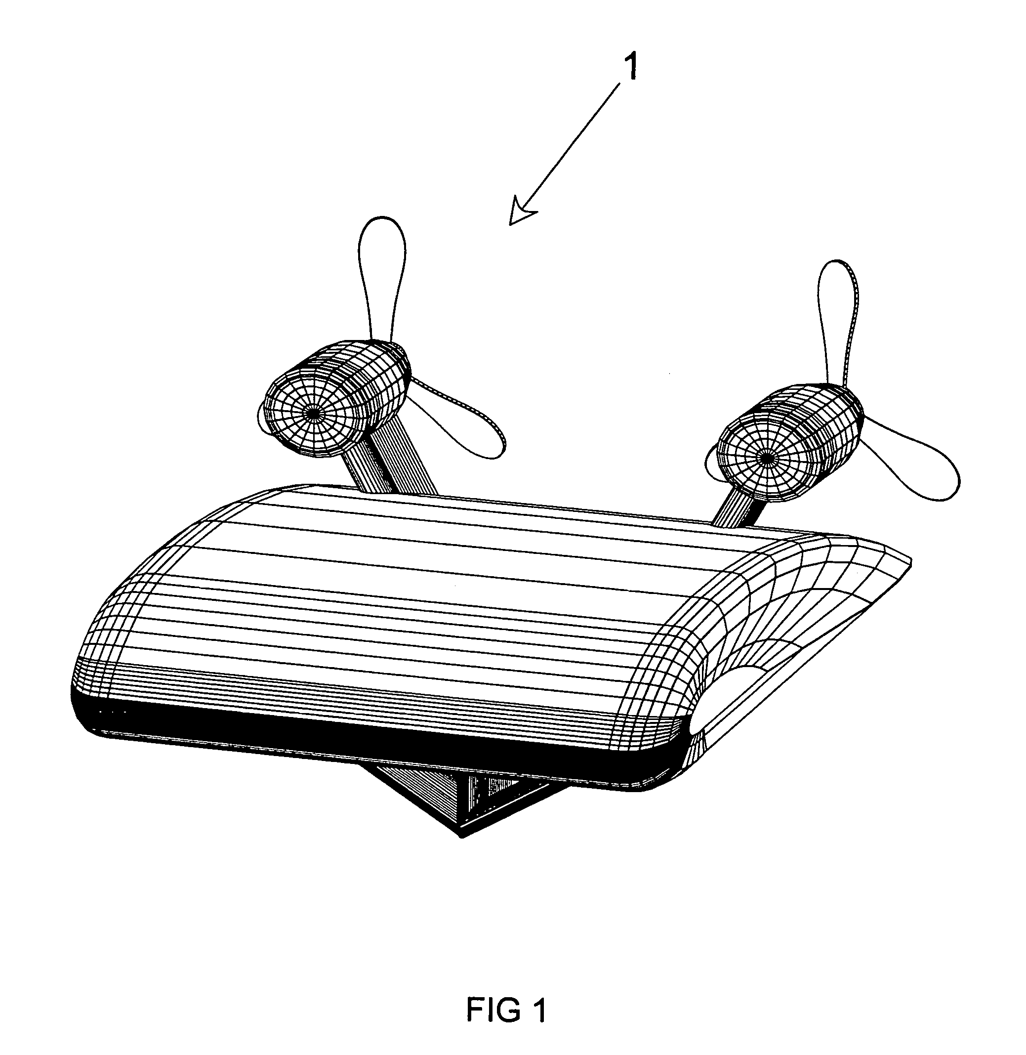
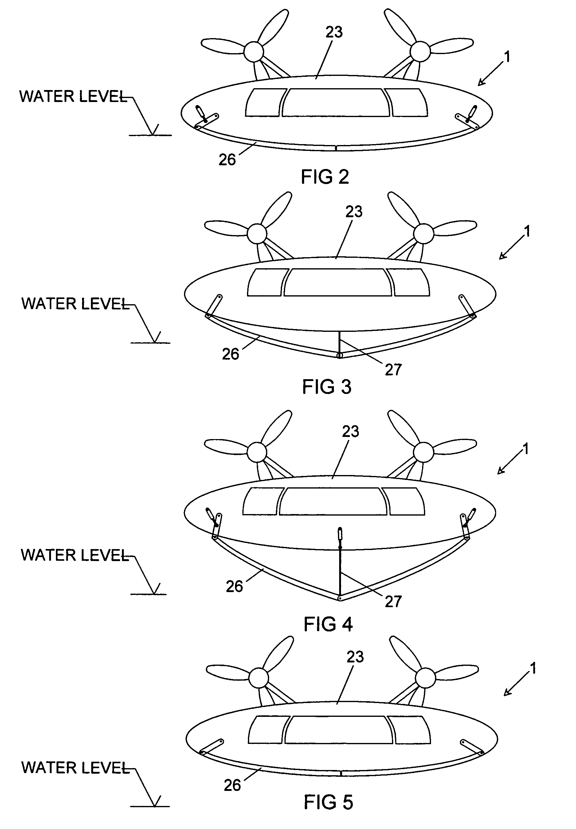
[0019]A watercraft 1 includes a streamlined hull 23 with a flying wing shape (airfoil) for maximum lift and minimum drag when operating in ground-effect mode. Cabin access is through a watertight side door 29.

Power

[0020]Control of the watercraft 1 includes of a plurality of aircraft-style engines, positioned outside the main hull in a nacelles 20 that also house fuel tanks. This separates fuel and engines from passengers for improved safety. The nacelles 20 are attached to angled struts 22 with an airfoil cross-section as illustrated in FIG. 7.

Control

[0021]At high speed, the angled struts 22 exert a self-righting force in the case of left or right tilt (roll motion). The distinct arrangement causes the lower side to provide more vertical force returning the watercraft 1 to level operation. Each engine is individually controlled, and fitted with individually controlled variable-pitch air propellers 21. At any given engine speed the thrust of each propeller 21 can be adjusted by ...


PUM


Abstract

A watercraft capable of operating in hydrofoil mode or ground-effect mode with self-righting retractable V-shaped foil, fiberoptic control systems, and a plurality of aircraft style engines with variable pitch propellers for speed and direction control. The V-shaped foil can be fully retracted into the hull allowing operation in shallow water, and the ability to execute a beach landing. Propeller pitch can be reversed allowing the craft to backup. Each engine and propeller can be controlled individually allowing rotating in-place for precise maneuvering control. The hull is a flying wing, airfoil shape for efficient high-speed operation. Engine nacelles are located on airfoil shaped struts, angled in a V-shape, for self-righting effect at high speed. Fuel tanks are within the nacelles, thus outside the main hull for safety.

Description

CROSS-REFERENCE TO RELATED APPLICATIONS[0001]This is a continuation-in-part application taking priority from Ser. No. 10 / 886,820 filed on Jul. 8, 2004 now abandoned.BACKGROUND OF THE INVENTION[0002]1. Field of the Invention[0003]This invention relates to the field of high-speed watercraft and more specifically to a hydrofoil watercraft with a V-shaped adjustable hydrofoil and ground-effect mode.[0004]2. Discussion of Prior Art[0005]Originally, hydrofoil watercraft consisted of a conventional boat design with a hydrofoil wing attached. These early designs failed to overcome the speed limitation of a foil-in-water due to high drag and cavitation as the foil reached certain speeds. They were vulnerable to floating debris, especially as speeds increased, posing a serious safety risk for occupants. In addition, the hull was not aerodynamically efficient further limiting high-speed operation. Later designs attempted to streamline the hull and incorporated overly complex retractable design...

Claims


Application Information

Patent Timeline
Patent Type & Authority Patents(United States)
IPC IPC(8): B63B1/30
CPCB60V1/08B63H7/02B63B1/285B60V3/06B63B1/30
Inventor BRASS, DWIGHT S.
Owner BRASS DWIGHT S
Why Eureka
Try Eureka