Wick arrangement for an anesthetic evaporator

a technology of anesthetic evaporators and wicks, which is applied in the direction of inhalators, respirators, lighting and heating apparatus, etc., can solve the problems of increased volume of evaporator chambers, adverse effect on the necessary constancy of anesthetic concentration, and additional increase of the volume of anesthetic evaporators

Inactive Publication Date: 2007-10-02
DRAGERWERK AG
View PDF6 Cites 7 Cited by
  • Summary
  • Abstract
  • Description
  • Claims
  • Application Information

AI Technical Summary

Benefits of technology

[0007]The advantage of the present invention is essentially that the flow through the wick arrangement takes place in so-called counterflow, so that the wick material can be utilized for enriching the gas flow with anesthetic vapor on both sides of the carrier material. The gas flow now comes into contact first with the wick material of one side of the carrier material and is then sent by a deflecting means to the other side of the carrier material and is further saturated with anesthetic vapor by the wick material present there. Compared with the prior-art wick arrangement with a wick wound helically, through which the flow is from the outside to the inside, the wick arrangement described in the present invention has a flow path that is twice as long and the path available for enriching the gas flow with anesthetic vapor is consequently twice as long as well. Due to the carrier material being coated with wick material on both sides, both sides of the carrier material can be utilized for evaporating the liquid anesthetic. The carrier material is designed such that it does not let through any appreciable gas flow, but the gas flow flows predominantly over the wick material.
[0008]The wick material may be permeable to both gas and liquid anesthetic. It preferably consists of a textile fabric or a sintered material. It is also possible to manufacture the wick entirely of a homogeneous material, e.g., a sintered material, which is porous and absorbent on its surface, but is impermeable to gas in the middle because of the greater compaction of the sintered material, so that the passage of gas through the wick is prevented from occurring or at least made difficult. The deflecting means, which deflects the gas flow from one side of the carrier material to the other side, is a baffle plate in the simplest case, with which the gas flow is deflected into the opposite direction of flow.
[0009]Since the wick is inserted into the housing of an anesthetic evaporator, the inner wall of the housing may assume the function of the baffle plate.
[0010]In an alternative wick arrangement according to the present invention, the wick is designed in the form of concentric ring channels, which are provided with a partition each blocking the gas. To deflect the gas flow, perforations are present in the ring channels, which are positioned in relation to the partitions such that reversal of the direction of flow is brought about by the partitions of the ring channels located adjacent to one another when the gas flow passes over into an adjacent ring channel. Together with the partitions, the perforations form the deflecting means.
[0011]Two wick sections formed by turning over the wick are advantageously provided, which are wound helically, where a first flow channel is located between the outer sides of the wick sections, which outer sides face one another, and a second flow channel extends along the inner sides of the wick sections. The flow reversal from the first flow channel into the second flow channel now takes place at the open ends of the wick sections over the inner wall of a housing, into which the wick is placed. If the folded-over end of the wick is located in the middle of an evaporator housing, i.e., if the wick is wound helically around the folded-over end, the gas can be introduced into the wick via the second flow channel in the area of the folded-over end of the wick. The gas will now flow between the wick sections through the second flow channel from the inside to the outside and is then deflected at the inner wall of the evaporator housing into the first flow channel and flows back into the middle in counterflow relative to the direction of flow in the second flow channel and is then fed therefrom as a gas flow enriched with anesthetic vapor to an anesthetic metering means.
[0012]To form the flow channels along the wick material, spacers are provided, which are arranged on both sides of the carrier material. The spacer may advantageously also be a coarse-meshed wire mesh, which is placed between the wick material.

Problems solved by technology

However, a large wick surface leads to a larger evaporator chamber volume in the prior-art anesthetic evaporator.
However, not only does a large evaporator chamber volume increase the volume of the anesthetic evaporator, but also has an adverse effect on the necessary constancy of the anesthetic concentration during changes in pressure, which occur during respiration.
Thus, the pressure compensation line must also be made correspondingly longer in case of a large evaporator chamber volume, which leads to an additional increase in the volume of the anesthetic evaporator.

Method used


Image

  • Wick arrangement for an anesthetic evaporator
  • Wick arrangement for an anesthetic evaporator
  • Wick arrangement for an anesthetic evaporator

Examples


Embodiment Construction

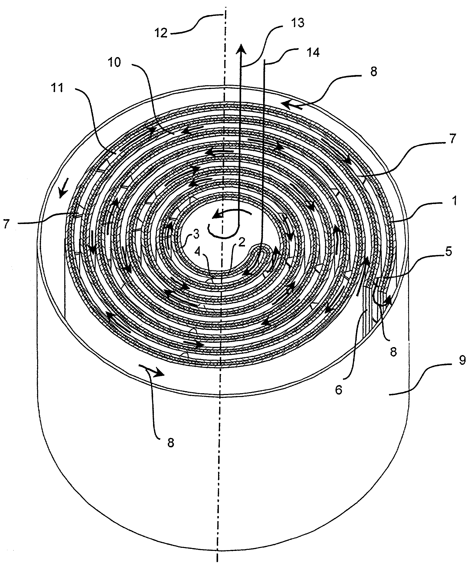
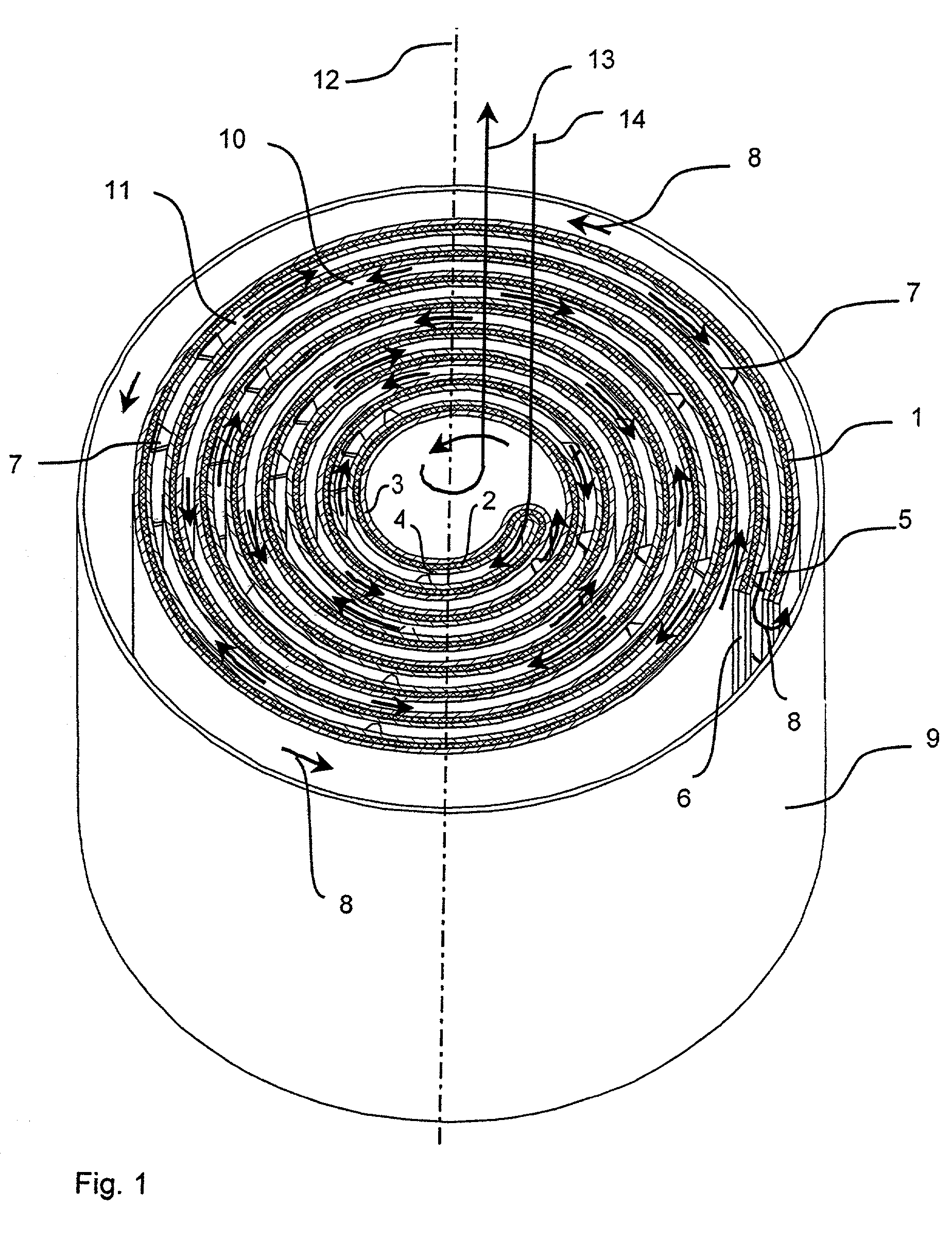
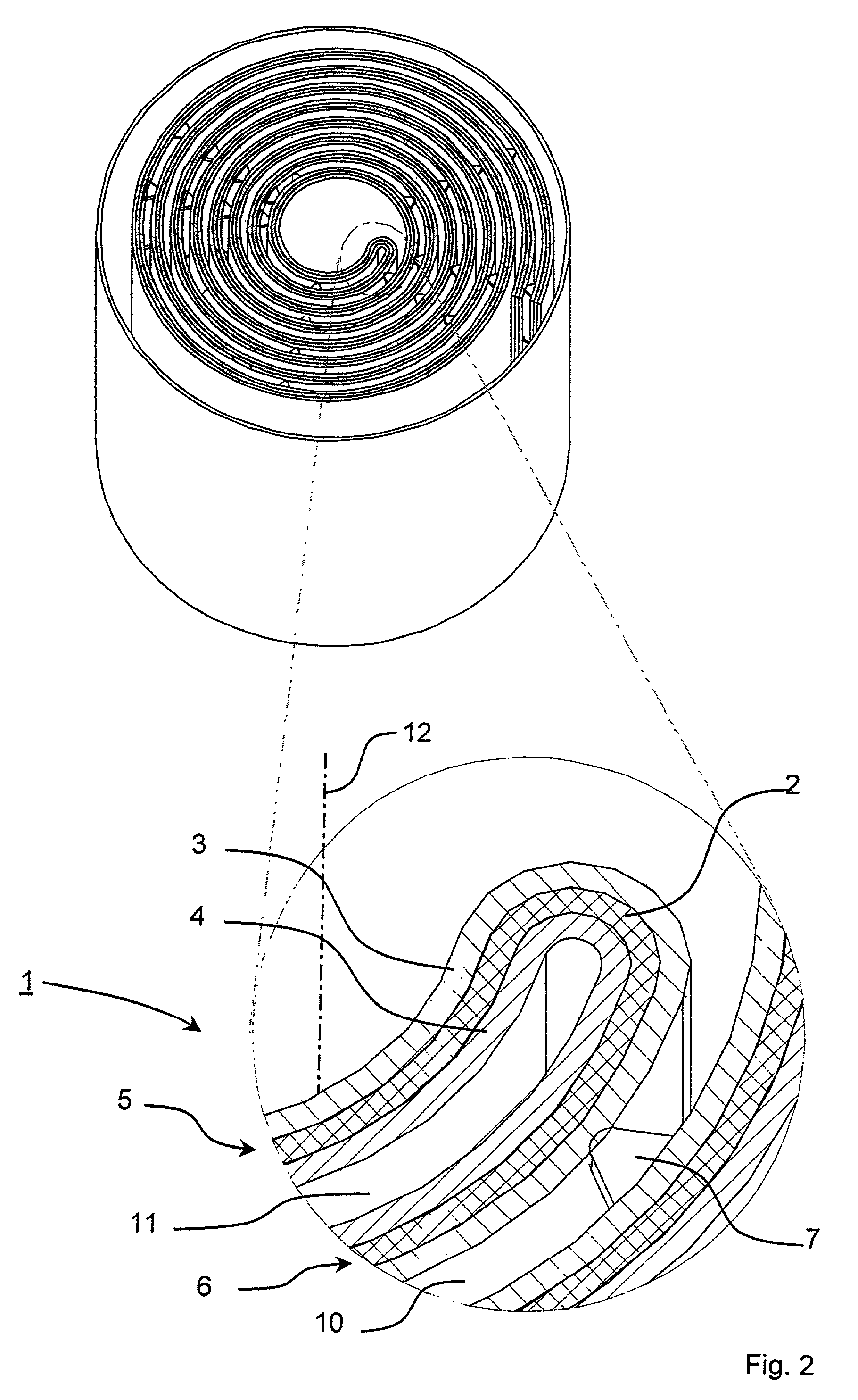
[0018]Referring to the drawings in particular, FIG. 1 schematically shows a perspective view of a wick 1, which comprises carrier material 2, which is bent over in a U-shaped pattern at a central axis 12 and is provided with wick material 3, 4 on both sides. A first wick section 5 and a second wick section 6, which are of equal size and are flatly in contact with one another, are formed by the folded-over wick 1. The carrier material 2 consists of special steel, while the wick materials are thin, absorbent nonwovens which are connected to the carrier material 2.

[0019]The wick 1 is accommodated in a cylindrical housing 9, which is partially filled with a liquid anesthetic, which is not shown in FIG. 1 and is to be evaporated. A first flow channel 10 is formed by the consecutive outer sides of the wick sections 5, 6 with the wick material 3. The inner sides of the wick sections 5, 6 with the wick material 4 form a second flow channel 11. A first gas channel 13 opens into the first flo...


PUM


Abstract

A wick arrangement for an anesthetic evaporator includes a wick with a carrier material (2) that is essentially impermeable to gas provided with wick material (3, 4) on both sides. A great path length is provided for saturating the gas with anesthetic vapor in the smallest possible installation volume by providing flow channels such as helical flow channels (10, 11) extending helically on both sides of the wick. The gas flow is led in counterflow in the flow channels (10, 11) by a housing (9).

Description

FIELD OF THE INVENTION[0001]The present invention pertains to a wick arrangement for an anesthetic evaporator and more particularly to a wick arrangement for an anesthetic evaporator provided with a wick material.BACKGROUND OF THE INVENTION[0002]An anesthetic evaporator has been known, in which the a gas flow entering a gas entry pipe branch of the anesthetic evaporator is divided into a so-called bypass gas flow and an evaporator chamber gas flow. The two gas flows are again united at a gas outlet pipe branch. The bypass gas flow returns directly to the gas outlet pipe branch via a bypass line, while the evaporator chamber gas flow is enriched with anesthetic vapor up to the saturation limit in an evaporator chamber. Different anesthetic concentrations can be set by changing the ratio of the two gas flows in relation to one another. Such an anesthetic evaporator has become known from EP 220 258 B1.[0003]A wick, which is rolled up helically, is immersed into liquid anesthetic and th...

Claims


Application Information

Patent Timeline
Patent Type & Authority Patents(United States)
IPC IPC(8): A61M15/00A61M16/00A61M16/10A61M16/18
CPCA61M16/18A61M16/1045Y10S165/398Y10S165/907
Inventor GIPPERT, KARL-LUDWIG
Owner DRAGERWERK AG
Why Eureka
Try Eureka