Eureka AIR delivers breakthrough ideas for toughest innovation challenges, trusted by R&D personnel around the world.

Energy-saving drive apparatus for DC loads

Inactive Publication Date: 2007-10-02
WU CHUN LIANG +1
View PDF1 Cites 2 Cited by
  • Summary
  • Abstract
  • Description
  • Claims
  • Application Information

AI Technical Summary

Benefits of technology

[0010]It is a primary object of the invention to eliminate the above-mentioned drawbacks and to provide an energy-saving drive apparatus for DC loads that includes an energy converter. Under the control of the energy converter, the load terminal obtains a feedback signal. Meanwhile, the signal voltage and current are unceasingly corrected according to the load feature in such a manner that the loads can also be driven under the state of low voltage and low current. In this way, an energy-saving, safe and eco-friendly usage is ensured. In addition, the overheat problem can be avoided.
[0011]In order to achieve the above-mentioned object, an energy-saving drive apparatus for DC loads in accordance with the invention includes a blocking oscillator, an amplifier, an AC-DC-converter, a voltage comparator, a current comparator, and a signal feedback circuit. The DC power produced by all kinds of batteries pass through the blocking oscillator and the amplifier to obtain an amplified signal voltage that is then converted into DC voltage and current. Meanwhile, the voltage comparator and the current comparator are connected at an output terminal of the AC-DC-converter. The signal feedback circuit obtains a load signal voltage from the load. After a feedback operation, a comparison voltage and a comparison current are transmitted to the input terminal of the voltage comparator and the current comparator. After the different signal voltages and currents are compared, analyzed, edited and sorted, a constant voltage circuit between the load and the voltage comparator as well as a constant current circuit between the load and the current comparator give out a corrected constant voltage value and a corrected constant current value, respectively, for re-driving the load. Therefore, the voltage and current impedance of the load can be matched to each other by the correcting process of the signal voltage and current for achieving an optimal and efficient power-saving output state.

Problems solved by technology

To the contrary, they can be problematic when used outdoors since they require a very long extension cord.
It is a time-wasting and labor-wasting task to establish an electric connection between the mini motor and the mains socket by the electric cord.
Besides, the electric cord will destroy the appearance of the environment.
However, the batteries have the restricted service life.
This does not meet the economic benefit.
However, there are many loads that are used outdoors and driven by low voltage and current.
However, high temperature will be created when LEDs light up for a long time, thereby affecting the luminance (Lu).
However, high temperature will be created in a short time by lighting up LEDs for a long time.
Accordingly, the luminance of LEDs will be lessened when a suitable cooling device is not available, thereby reducing their operational reliability.
Furthermore, some DC loads like mini-motors used as power source for certain products don't achieve the expected power efficiency since the DC power source can't ensure a voltage and current impedance matching of the load at the output terminal according to the load features for minimizing the loss.

Method used


Image

  • Energy-saving drive apparatus for DC loads
  • Energy-saving drive apparatus for DC loads
  • Energy-saving drive apparatus for DC loads

Examples


Embodiment Construction

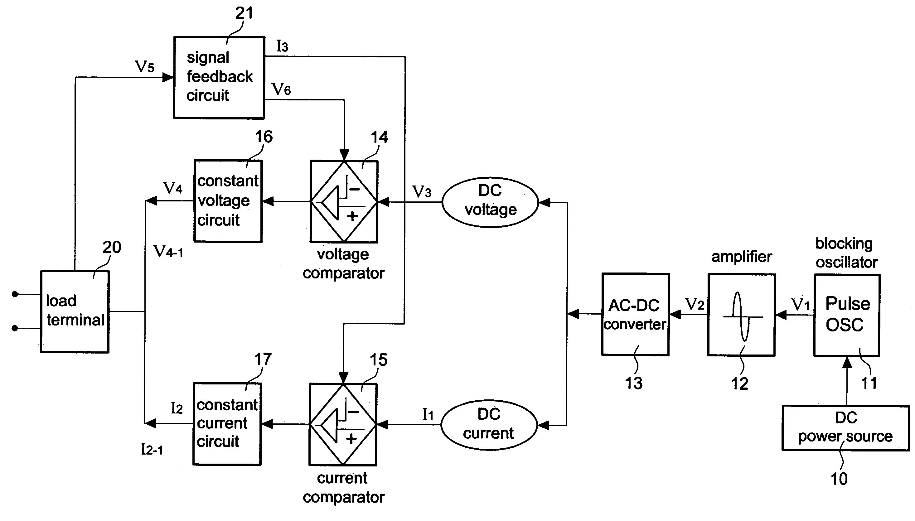
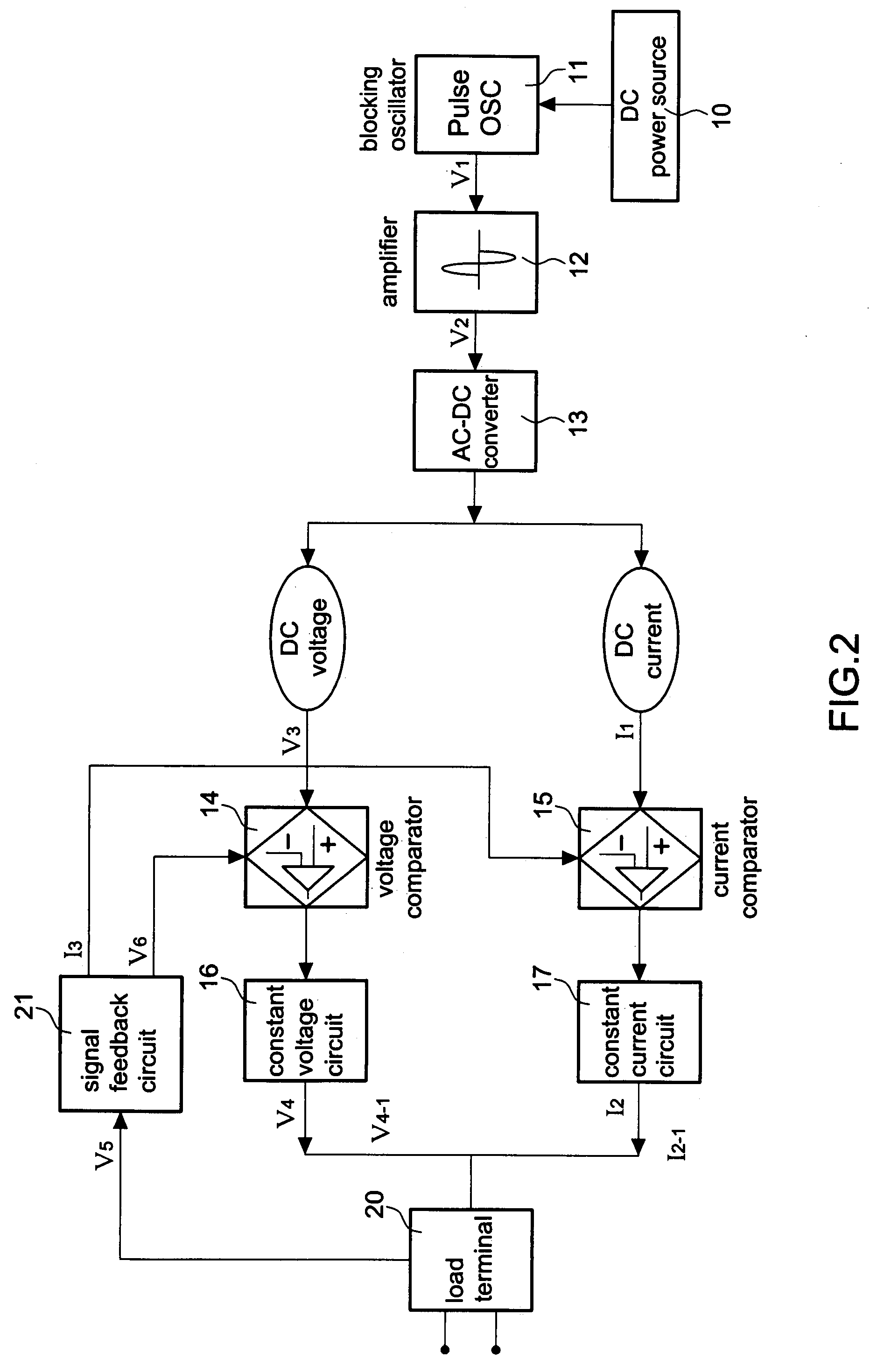
[0016]First of all, referring to FIG. 2, an energy-saving drive apparatus in accordance with the invention includes a DC power source 10 for supplying a DC voltage to a DC load 20; a blocking oscillator 11 for converting the electric current inputted from the DC power source 10 into a pulse signal voltage V1; an amplifier 12 connected at an output terminal of the blocking oscillator 11 for amplifying the pulse signal voltage V1 so as to obtain an amplified signal voltage V2; an AC-DC-converter 13 connected at an output terminal of the amplifier 12 for converting the amplified signal voltage V2 into an initial DC voltage V3 and an initial DC current I1; a voltage comparator 14 connected at an output terminal of the AC-DC-converter 13 for comparing the inputted initial DC voltage V3 with the voltage signal at another output terminal and for supplying a constant voltage V4 to the load; a current comparator 15 connected at an output terminal of the AC-DC-converter 13 for comparing the i...


PUM


Abstract

Energy-saving drive apparatus for DC loads including a blocking oscillator, an amplifier, an AC-DC-converter, a voltage comparator, a current comparator, and a signal feedback circuit. The DC power produced by all kinds of batteries pass through the blocking oscillator and the amplifier to obtain an amplified signal voltage that is then converted into DC voltage and current. Meanwhile, the voltage comparator and the current comparator are connected at an output terminal of the AC-DC-converter. The signal feedback circuit obtains a load signal voltage from the load. After a feedback operation, a comparison voltage and a comparison current are transmitted to the input terminal of the voltage comparator and the current comparator. After the different signal voltages and currents are compared, analyzed, edited and sorted, a constant voltage circuit between the load and the voltage comparator as well as a constant current circuit between the load and the current comparator give out a corrected constant voltage value and a corrected constant current value, respectively, for re-driving the load. Therefore, the voltage and current impedance of the load can be matched to each other by the correcting process of the signal voltage and current for achieving an optimal and efficient power-saving output state.

Description

BACKGROUND OF THE INVENTION[0001]1. Field of the Invention[0002]The invention relates to an energy-saving drive apparatus for DC loads, and more particularly to an energy-saving drive apparatus that ensures a full use of power by the control of an energy converter for achieving the energy-saving effect.[0003]2. Description of the Related Art[0004]Both the light energy and the electric energy are indispensable for the modern life. For example, the outdoor Christmas lamps require an electric cord for transmitting the electric energy to the lamps for lighting purpose. Moreover, many objects in our daily life also require electric energy. They are ready and practical for indoor use when they are connected via electric cords to mains socket. To the contrary, they can be problematic when used outdoors since they require a very long extension cord. Among these objects, they may require a mini motor as drive source. It is a time-wasting and labor-wasting task to establish an electric connec...

Claims


Application Information

Patent Timeline
IPC IPC(8): H02J9/02
CPCH02M3/33507
Inventor WU, CHUN-LIANGPOLLEY, WILLIAM F.
Owner WU CHUN LIANG
Why Eureka
Eureka Blog
Learn More