Automatic bias control circuit for linear power amplifiers

a linear power amplifier and automatic bias control technology, applied in the direction of amplifier modification to reduce non-linear distortion, single-ended push-pull amplifiers, gain control, etc., can solve the problem of increasing current, conventional linear power amplifiers can significantly exceed the minimum specified linearity requirements at low output power levels, and conventional linear power amplifiers can consume more current than is necessary at low power output levels. to achieve the effect of reducing current consumption

Active Publication Date: 2007-10-02
SKYWORKS SOLUTIONS INC
View PDF3 Cites 25 Cited by
  • Summary
  • Abstract
  • Description
  • Claims
  • Application Information

AI Technical Summary

Problems solved by technology

Since linear power amplifiers, such as linear power amplifiers used in cellular handsets as well as other wireless applications, typically consume a significant amount of battery power, they are generally designed to draw the least amount of current possible.
As a result, the conventional linear power amplifier can significantly exceed the minimum specified linearity requirements at low output power levels.
However, since there is typically a tradeoff between current consumption and linearity (i.e. an increase or decrease in linearity is typically accompanied by a respective increase or decrease in current consumption), the conventional linear power amplifier can consume more current than is necessary at low power output levels.
By consuming excessive current at lower power output levels, the conventional linear power amplifier, such as a conventional linear power amplifier used in cellular handsets as well as other wireless devices, can cause an undesirable reduction in battery life.

Method used


Image

  • Automatic bias control circuit for linear power amplifiers
  • Automatic bias control circuit for linear power amplifiers
  • Automatic bias control circuit for linear power amplifiers

Examples


Embodiment Construction

[0012]The present invention is directed to an automatic bias control circuit for power amplifiers. The following description contains specific information pertaining to the implementation of the present invention. One skilled in the art will recognize that the present invention may be implemented in a manner different from that specifically discussed in the present application. Moreover, some of the specific details of the invention are not discussed in order not to obscure the invention.

[0013]The drawings in the present application and their accompanying detailed description are directed to merely exemplary embodiments of the invention. To maintain brevity, other embodiments of the present invention are not specifically described in the present application and are not specifically illustrated by the present drawings.

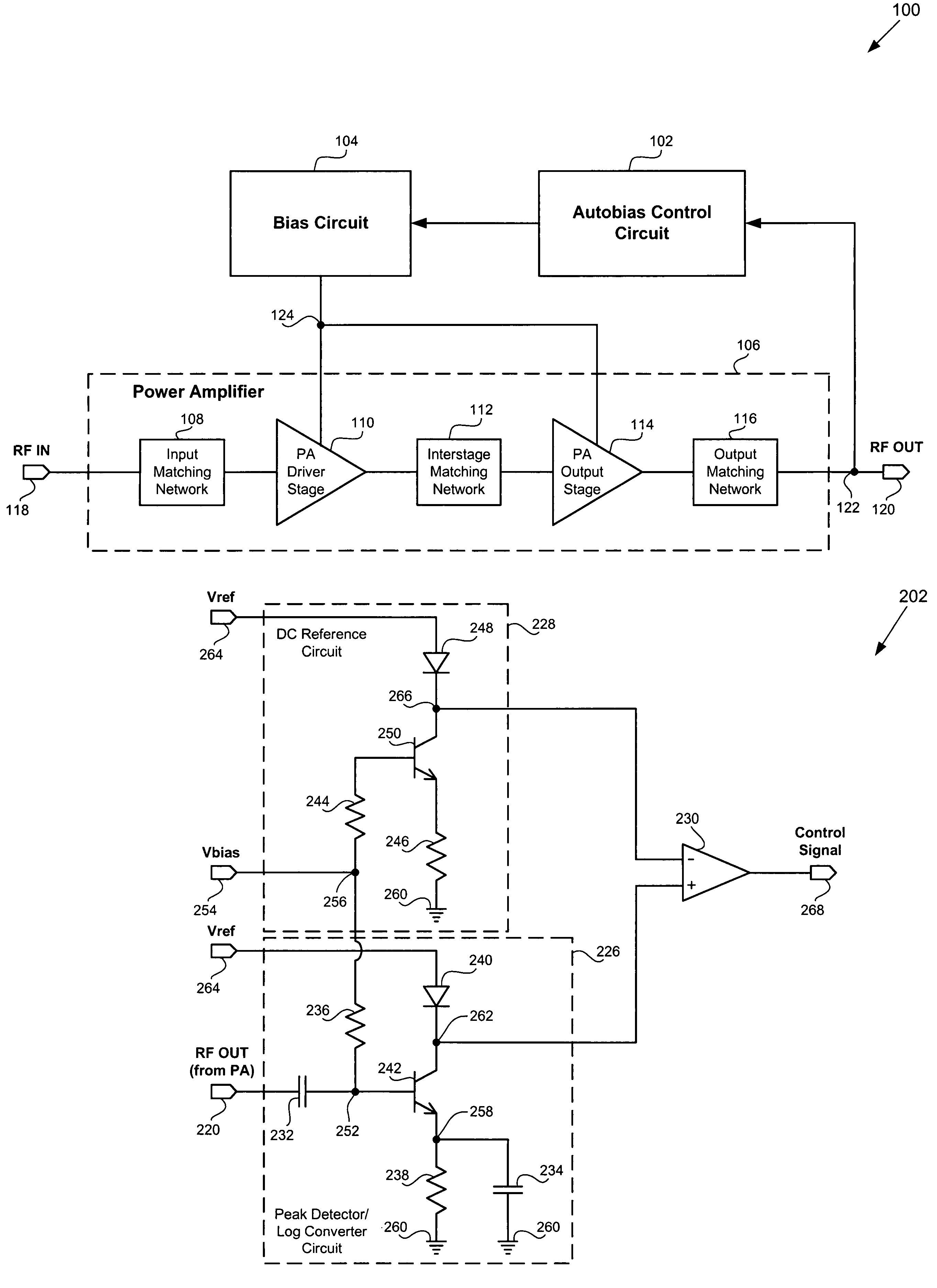
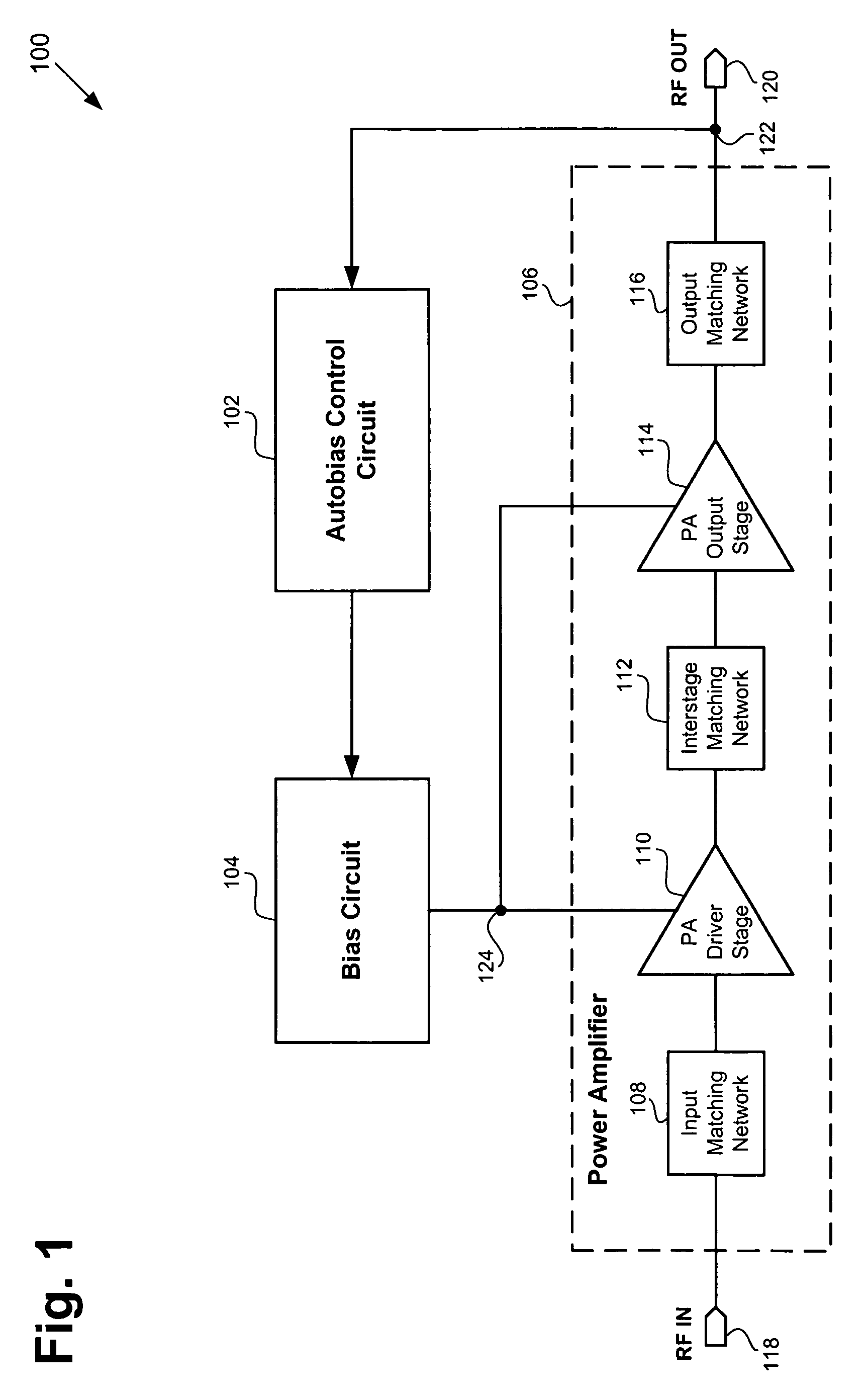
[0014]FIG. 1 shows a block diagram of an exemplary amplification module including an exemplary automatic bias control circuit, an exemplary analog bias circuit, and an ...


PUM


Abstract

According to an exemplary embodiment, an amplification module includes a power amplifier configured to receive an RF input signal and provide an RF output signal. The amplification module further includes an autobias control circuit configured to receive and convert the RF output signal to a control signal. The control signal can cause the power amplifier to have a quiescent current that increases substantially linearly in response to an increase in the RF output power of the RF output signal. The autobias control circuit can include a peak detector / log converter circuit coupled to a first input of a differential amplifier, where the differential amplifier outputs the control signal. The autobias control circuit can further include a DC reference circuit coupled to a second input of the differential amplifier. The amplification module further includes an analog bias circuit coupling the control voltage to a bias input of said power amplifier.

Description

BACKGROUND OF THE INVENTION[0001]1. Field of the Invention[0002]The present invention is generally in the field of electrical circuits. More particularly, the invention is in the field of power amplifiers.[0003]2. Background Art[0004]Power amplifiers, such as linear power amplifiers used in cellular handsets, are required to maintain a minimum specified linearity, which is defined by the Federal Communications Commission (“FCC”) or by customer specifications. Since linear power amplifiers, such as linear power amplifiers used in cellular handsets as well as other wireless applications, typically consume a significant amount of battery power, they are generally designed to draw the least amount of current possible. However, the goal of minimum current consumption must be achieved while meeting the minimum specified linearity requirements. Since it is difficult to meet linearity requirements at the highest output power that the linear power amplifier is required to deliver, a conventi...

Claims


Application Information

Patent Timeline
Patent Type & Authority Patents(United States)
IPC IPC(8): H03F3/04
CPCH03F1/0261H03F1/0272H03F1/30H03F1/32H03F2200/99H03F2200/435H03F2200/78H03F3/30
Inventor RIPLEY, DAVID S.ANDRYS, PAUL R.NELLIS, KEITH
Owner SKYWORKS SOLUTIONS INC
Why Eureka
Try Eureka