Display method of spatial data relationships

a technology of spatial data and relationship, applied in the field of spatial data relationship display method, can solve the problem of difficult selection of user's desired objects in the above-mentioned field

Inactive Publication Date: 2007-10-02
HITACHI SOFTWARE ENG
View PDF16 Cites 12 Cited by
  • Summary
  • Abstract
  • Description
  • Claims
  • Application Information

AI Technical Summary

Benefits of technology

[0007]Thus, the present invention provides an interface in which when different organizations or enterprises desire to share their held map information therebetween, meta data describing the property of each map information is interpreted to make the association of objects between its own organization and another organization and the procedure for unification for differences in coordinate system and unit therebetween, thereby allowing a user to decide the optimum relationship easily.

Problems solved by technology

Accordingly, the above-mentioned selection of user's desired objects is not easy.

Method used


Image

  • Display method of spatial data relationships
  • Display method of spatial data relationships
  • Display method of spatial data relationships

Examples


Embodiment Construction

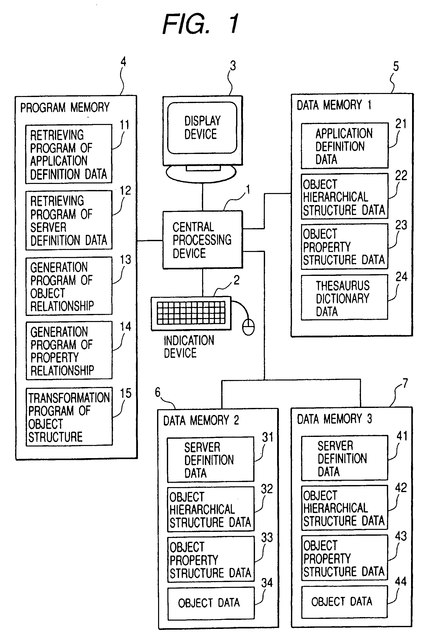
[0026]Embodiments of the present invention will now be described. FIG. 1 is a diagram showing the construction of a system for performing a relationship display processing according to the present invention. Reference numeral 1 denotes a central processing device for performing each program, numeral 2 an indication device which a user operates, numeral 3 a display device for displaying the result of execution of each program, numeral 4 a program memory for storing programs required for processings performed by the central processing device 1, and numerals 5, 6 and 7 data memories for storing data used by those programs.

[0027]The program memory 4 is stored with four types of programs including an application definition data retrieving program 11 for retrieving each data from the data memory 5, a server definition data retrieving program 12 for retrieving each data from the data memory 6 or 7, an object relationship generation program 13 for generating relationships between objects de...


PUM


Abstract

For interactive operation between different enterprises or organizations, it is necessary to provide high-quality map information by not only displaying the results of retrieval from the map information servers of those organizations in a superimposed manner but also performing distributed retrieval on the basis of a relationship matched in sense between the servers. Thus, an interface is provided in which the optimum relationships between objects provided from the map servers distributed on the Internet environment and objects defined by a desired application are generated and a work of confirmation and modification by a user can easily be done. Thereby, a cost required for a complicated relating procedure indispensable to an interactive operating system is reduced.

Description

BACKGROUND OF THE INVENTION[0001]Public utility enterprises for electric supply, gas supply, communication service, etc. and the waterworks / sewerage management divisions, public works divisions, etc. of local governments need maps and facility drawings for performing the maintenance and management of their facilities. Up to date, such enterprises and local governments have proceeded with data reduction or consolidation through the digitalization of maps and facility drawings.[0002]On the other hand, the progress of network-related technologies represented by optical communication networks, ATM and so on is bringing forth the recent situation in which the communication of a large volume of data on the Internet environment is enabled. Therein, the handling of map information requiring a large capacity is now realizable.[0003]In such circumstances, it is desired that maps and facility drawings managed by individual organizations are communized through the Internet to improve the effici...

Claims


Application Information

Patent Timeline
Patent Type & Authority Patents(United States)
IPC IPC(8): G06F15/00G06F17/00G06F17/30
CPCG06F17/30241G06F16/29
Inventor TANIZAKI, MASAAKISHIMADA, SHIGERUWATANABE, KAZUNORIISHII, AKIRA
Owner HITACHI SOFTWARE ENG
Why Eureka
Try Eureka