
Method and apparatus for determining the deflection of a fastener

a fastener and deflection technology, applied in the direction of screws, force measurement by measuring optical property variation, instruments, etc., can solve the problems of unsuitable moving components, bending of bending rods, and known apparatuses that are not suitable for moving components, etc., to achieve high analysis velocities and increase throughput

Active Publication Date: 2007-10-09
KAMAX HLDG
View PDF22 Cites 8 Cited by
  • Summary
  • Abstract
  • Description
  • Claims
  • Application Information

AI Technical Summary

Benefits of technology

The present invention relates to a method and apparatus for determining the deflection of a fastener in two perpendicular planes. The method involves recording two images of the fastener in two different directions and comparing them to determine the deviation of the fastener from its ideal position. The apparatus includes two cameras that capture images of the fastener in two directions, and a computer program that analyzes the images and calculates the deflection of the fastener. The technical effect of this invention is to provide a cost-efficient and effective way to measure the deflection of fasteners during their movement in the material flow.

Problems solved by technology

Thus, it is not suitable for moving components which are to be analyzed during material flow.
During bending of the cylinder, the bending rod is subjected with a bending force and with bending torque which results in bending of the bending rod.
The known apparatus is not suitable for moving components which are to be analyzed during material flow.

Method used


Image

  • Method and apparatus for determining the deflection of a fastener
  • Method and apparatus for determining the deflection of a fastener
  • Method and apparatus for determining the deflection of a fastener

Examples


Embodiment Construction

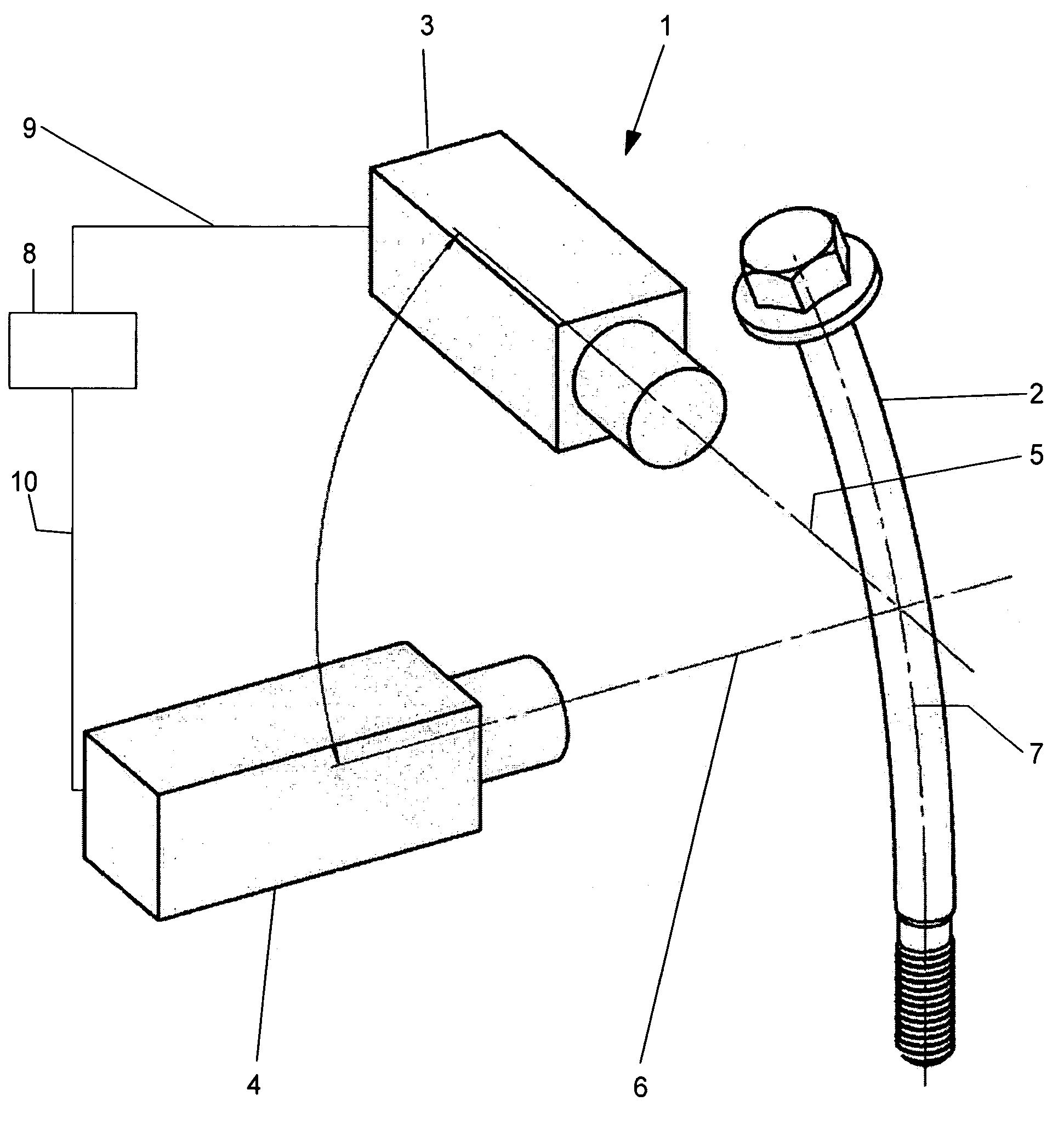
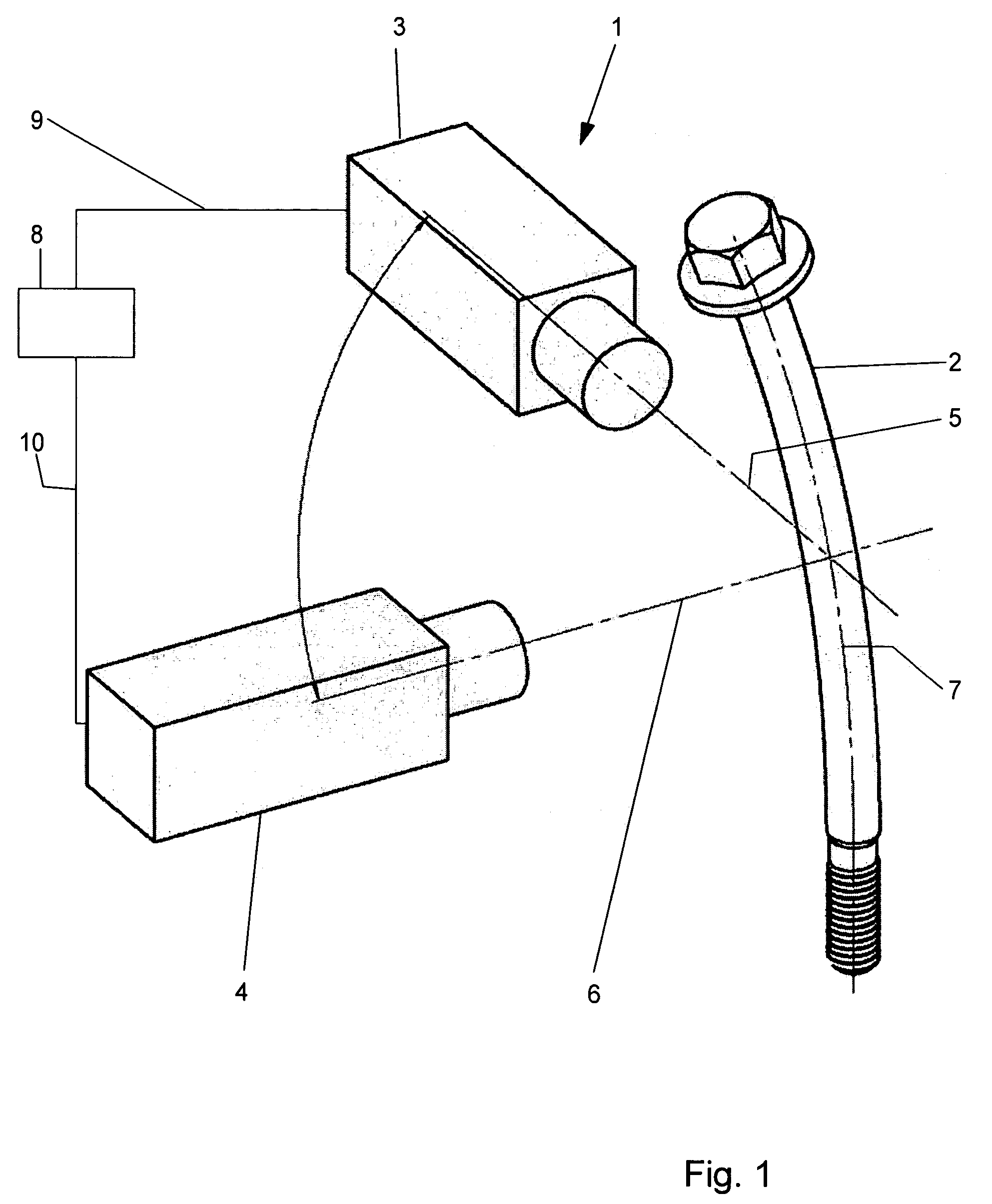
[0056]Referring now in greater detail to the drawings, FIG. 1 illustrates the general design of a novel apparatus 1 for determining the deflection of a fastener 2. The apparatus 1 is only schematically illustrated. The detailed technical design of the wiring for transmitting and evaluating the optical signals is known to a person with skill in the art such that it does not need to be explained herein in greater detail.

[0057]The apparatus 1 includes a first camera 3 for taking a first image of the fastener 2. Furthermore, there is a second camera 4 for taking a second image of the fastener 2. The camera 3 has an optical axis 5, and the camera 4 has an optical axis 6. The optical axis 6 of the second camera 4 is located to be substantially perpendicular to the optical axis 5 of the first camera 3. The optical axes 5, 6 of the cameras 3, 4 approximately intersect in the longitudinal axis 7 of the fastener 2. The apparatus 1 further includes a unit 8. The unit 8 serves to evaluate the s...


PUM


Abstract

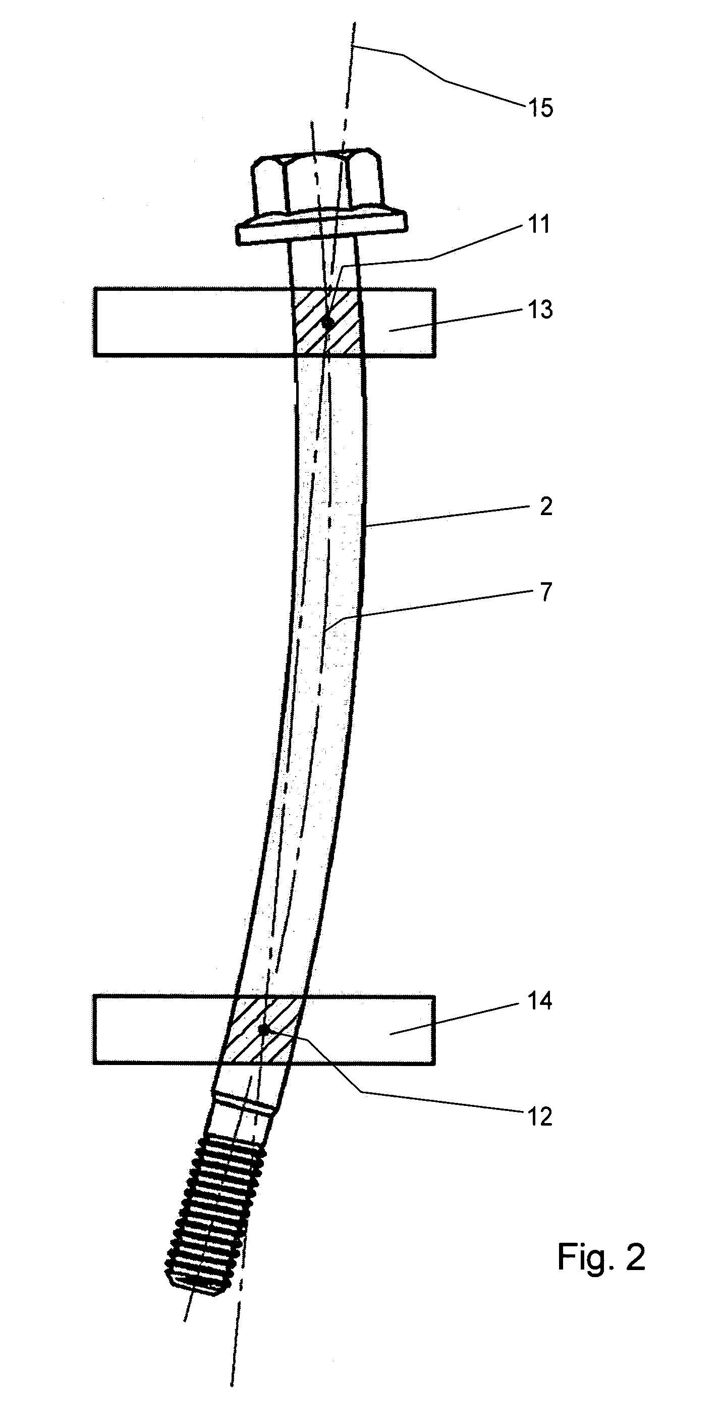
A method and an apparatus serve for determining the deflection of a fastener, especially a screw. The method includes the steps of (a) recording a first image of the fastener with a first camera; (b) determining two first reference points of the fastener in the first image for determining a first reference axis of the fastener, the first reference axis extending through the two first reference points; (c) determining a first inspection point in a first inspection region in the first image; (d) comparing the position of the first inspection point with the respective position of the first reference axis for determining a first deviation; (e) recording a second image of the fastener with a second camera, the optical axis of the second camera being substantially perpendicular to the optical axis of the first camera, the optical axes of the first and second camera approximately intersecting in the longitudinal axis of the fastener; (f) determining two second reference points of the fastener in the second image for determining a second reference axis of the fastener, the second reference axis extending through the two second reference points; (g) determining a second reference point in a second inspection region in the second image; and (h) comparing the position of the second inspection point with the respective position of the second reference axis for determining a second deviation.

Description

CROSS REFERENCE TO RELATED APPLICATIONS[0001]This application claims priority to co-pending German Patent Application No. DE 10 2005 000 610.8 entitled “Verfahren und Vorrichtung zum Bestimmen der Durchbiegung eines Verbindungselements”, filed Jan. 03, 2005.FIELD OF THE INVENTION[0002]The present invention generally relates to a method and an apparatus for determining the deflection of a fastener. More particularly, the present invention relates to a method and an apparatus for determining the deflection of a screw.[0003]The manufacture of elongated components or elements often results in undesired bending and deflection, respectively, of the components. Especially in case the component is a fastener, one main reason for this deflection is thermal treatment of the component during which the fastener is heated to reach a high temperature. Consequently, strength and stability of the material of the fastener are substantially reduced. These bending effects and deflections, respectively...

Claims


Application Information

Patent Timeline
Patent Type & Authority Patents(United States)
IPC IPC(8): F16B31/02
CPCG01B11/245G01B11/2425
Inventor HARTMANNDEEG, WOLFGANG
Owner KAMAX HLDG
Learn More