
Method and apparatus for determining the deflection of a fastener

Active Publication Date: 2006-07-06
KAMAX HLDG
View PDF3 Cites 8 Cited by
  • Summary
  • Abstract
  • Description
  • Claims
  • Application Information

AI Technical Summary

Benefits of technology

[0020] With the novel method and apparatus for determining the deflection of a fastener, it is possible to determine the deflection of the fastener during its movement in the material flow in an effective and cost-efficient way.
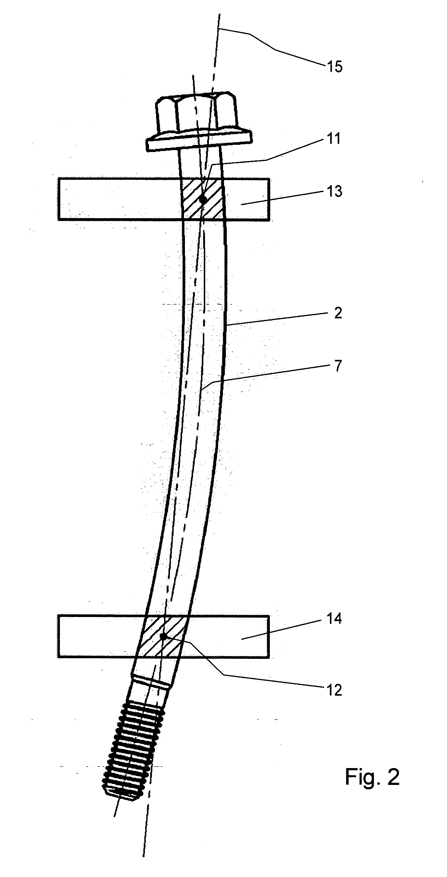
[0029] Furthermore, an inspection region or portion is defined in the first camera image. The maximum deflection of the fastener will practically be located approximately in the center region of the fastener. In case the reference portions are located at the axial ends of the fastener to be measured, the inspection region will be defined approximately in the center of the fastener. However, in case the reference regions are located to be adjacent and at a defined distance from one axial end of the fastener, it is preferred to locate the inspection region at the opposite axial end of the fastener. Due to the fact that the inspection region is especially defined in the recorded image by software, a change from one arrangement to the other is possible without difficulty.
[0031] To prevent negative influences concerning the exactness, for example influences by dirt particles, it has been found to be advantageous to determine the two outer contours of the component in the inspection region and to even out the shape of the contour before determining the inspection point. However, other algorithms are also possible.
[0043] An exact alignment of the fastener with respect to the cameras is not required. In this way, it is possible to analyze the fasteners during their linear movement within a material flow. This allows for high analyzing velocities and thus increased throughput. Due to automatic evaluation of the results of the analysis and a comparison with the desired value under consideration of a tolerance, it is possible to produce a go / no-go signal with which a respectively controlled ejector automatically singles out the fasteners after completion of the analysis.
[0044] To prevent mutual influence of the two cameras being arranged to be substantial perpendicular with respect to one another due to the illuminating unit of the respective other camera, it is possible to use polarization filters, for example. Especially in case of light or dark reflecting fasteners, one attains decoupling of the two optical systems. For each one of the two cameras, preferably a polarization filter being oriented in the same way is used, the polarization filter being designed and arranged to only allow for passage of the light of the associated source of light, whereas the light of the other optical system is prevented from passage.

Problems solved by technology

Thus, it is not suitable for moving components which are to be analyzed during material flow.
During bending of the cylinder, the bending rod is subjected with a bending force and with bending torque which results in bending of the bending rod.
The known apparatus is not suitable for moving components which are to be analyzed during material flow.

Method used


Image

  • Method and apparatus for determining the deflection of a fastener
  • Method and apparatus for determining the deflection of a fastener
  • Method and apparatus for determining the deflection of a fastener

Examples


Embodiment Construction

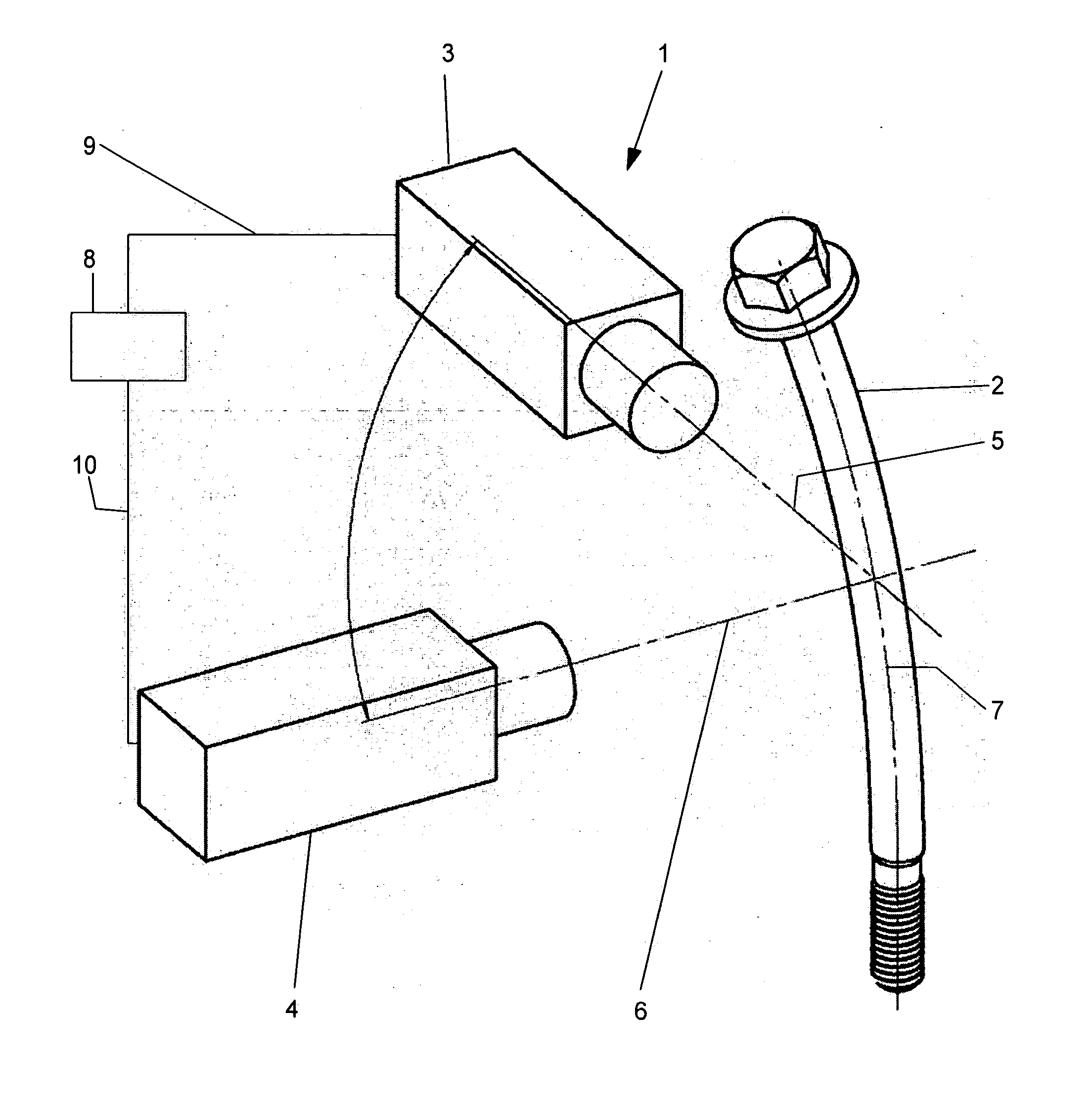
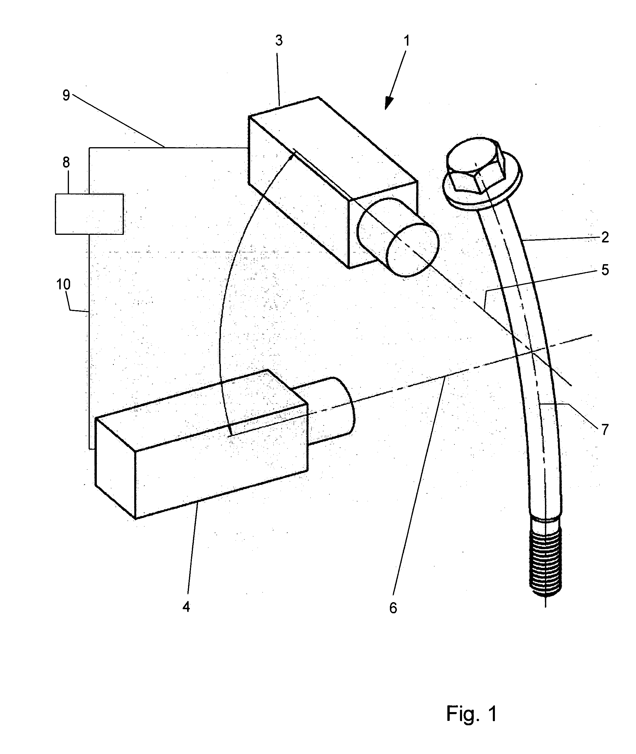
[0056] Referring now in greater detail to the drawings, FIG. 1 illustrates the general design of a novel apparatus 1 for determining the deflection of a fastener 2. The apparatus 1 is only schematically illustrated. The detailed technical design of the wiring for transmitting and evaluating the optical signals is known to a person with skill in the art such that it does not need to be explained herein in greater detail.

[0057] The apparatus 1 includes a first camera 3 for taking a first image of the fastener 2. Furthermore, there is a second camera 4 for taking a second image of the fastener 2. The camera 3 has an optical axis 5, and the camera 4 has an optical axis 6. The optical axis 6 of the second camera 4 is located to be substantially perpendicular to the optical axis 5 of the first camera 3. The optical axes 5, 6 of the cameras 3, 4 approximately intersect in the longitudinal axis 7 of the fastener 2. The apparatus 1 further includes a unit 8. The unit 8 serves to evaluate th...


PUM


Abstract

A method and an apparatus serve for determining the deflection of a fastener, especially a screw. The method includes the steps of (a) recording a first image of the fastener with a first camera; (b) determining two first reference points of the fastener in the first image for determining a first reference axis of the fastener, the first reference axis extending through the two first reference points; (c) determining a first inspection point in a first inspection region in the first image; (d) comparing the position of the first inspection point with the respective position of the first reference axis for determining a first deviation; (e) recording a second image of the fastener with a second camera, the optical axis of the second camera being substantially perpendicular to the optical axis of the first camera, the optical axes of the first and second camera approximately intersecting in the longitudinal axis of the fastener; (f) determining two second reference points of the fastener in the second image for determining a second reference axis of the fastener, the second reference axis extending through the two second reference points; (g) determining a second reference point in a second inspection region in the second image; and (h) comparing the position of the second inspection point with the respective position of the second reference axis for determining a second deviation.

Description

CROSS REFERENCE TO RELATED APPLICATIONS [0001] This application claims priority to co-pending German Patent Application No. DE 10 2005 000 610.8 entitled “Verfahren und Vorrichtung zum Bestimmen der Durchbiegung eines Verbindungselements”, filed Jan. 03, 2005. FIELD OF THE INVENTION [0002] The present invention generally relates to a method and an apparatus for determining the deflection of a fastener. More particularly, the present invention relates to a method and an apparatus for determining the deflection of a screw. [0003] The manufacture of elongated components or elements often results in undesired bending and deflection, respectively, of the components. Especially in case the component is a fastener, one main reason for this deflection is thermal treatment of the component during which the fastener is heated to reach a high temperature. Consequently, strength and stability of the material of the fastener are substantially reduced. These bending effects and deflections, respe...

Claims


Application Information

Patent Timeline
IPC IPC(8): F16B31/02
CPCG01B11/245G01B11/2425
Inventor HARTMANNDEEG, WOLGANG
Owner KAMAX HLDG
Learn More