Micro-electro-mechanical switch and a method of using and making thereof

a micro-electro-mechanical switch and switch technology, applied in the field of micro-electro-mechanical switches, can solve the problems of preventing their more widespread use, affecting the switching speed or response, and unable to apply a force in the opposite direction to release the mems, etc., to achieve the effect of low parasitic capacitance and high switching speed or respons

Inactive Publication Date: 2007-10-09
ROCHESTER INSTITUTE OF TECHNOLOGY
View PDF227 Cites 44 Cited by
  • Summary
  • Abstract
  • Description
  • Claims
  • Application Information

AI Technical Summary

Benefits of technology

[0007]A switch in accordance with one embodiment of the present invention includes at least one portion of a conductive line in the chamber, a beam with imbedded charge, and control electrodes. The beam has a conductive section which is positioned in substantial alignment with the at least one portion of the conductive line. The conductive section of the beam has an open position spaced away from the conductive line and a closed position on the conductive line. Each of the control electrodes is spaced away from an opposing side of the beam to control movement of the beam.
[0008]A method for making a switch in accordance with another embodiment of the present invention includes forming a chamber in a switch housing, forming separated portions of a conductive line in the chamber, forming a beam with imbedded charge which extends into the chamber, and forming a pair of control electrodes spaced away from opposing sides of the beam. The beam has a conductive section located at or adjacent an edge of the beam and which is positioned in substantial alignment with the separated portions of the conductive line. The conductive section of the beam has an open position spaced away from the separated portions of the conductive line and a closed position on a part of each of the separated portions of the conductive line to couple the separated portions of the conductive line together.
[0009]A method of using a switch in accordance with another embodiment of the present invention includes applying a first potential to control electrodes and moving a conductive section on a beam to one of an open position spaced away from at least one portion of a conductive line or a closed position on the at least one portion of the conductive line in response to the applied first potential. The beam has imbedded charge and a conductive section that is located at or adjacent an edge of the beam and is positioned in substantial alignment with the at least one portion of a conductive line. Each of the control electrodes is spaced away from an opposing side of the beam to control movement of the beam.
[0010]A method for making a switch in accordance with another embodiment of the present invention includes forming at least one portion of a conductive line, forming a beam with imbedded charge, and forming control electrodes. The beam has a conductive section which is positioned in substantial alignment with the at least one portion of the conductive line. The conductive section of the beam has an open position spaced away from the at least one portion of the conductive line and a closed position on the at least one portion of the conductive line. Each of the control electrodes is spaced away from an opposing side of the beam to control movement of the beam.
[0011]A method for making a switch in accordance with another embodiment of the

Problems solved by technology

Although these MEMS switches work problems have prevented their more widespread use.
For example, one problem with cantilever type MEMS is that they often freeze into a closed position due to a phenomenon known as stiction.
These cantilever type MEMS may be actuated by electrostatic forces, however there is no convenient way to apply a force in the opposite direction to release the MEMS to the open position.
Unfortunately, th

Method used


Image

  • Micro-electro-mechanical switch and a method of using and making thereof
  • Micro-electro-mechanical switch and a method of using and making thereof
  • Micro-electro-mechanical switch and a method of using and making thereof

Examples


Embodiment Construction

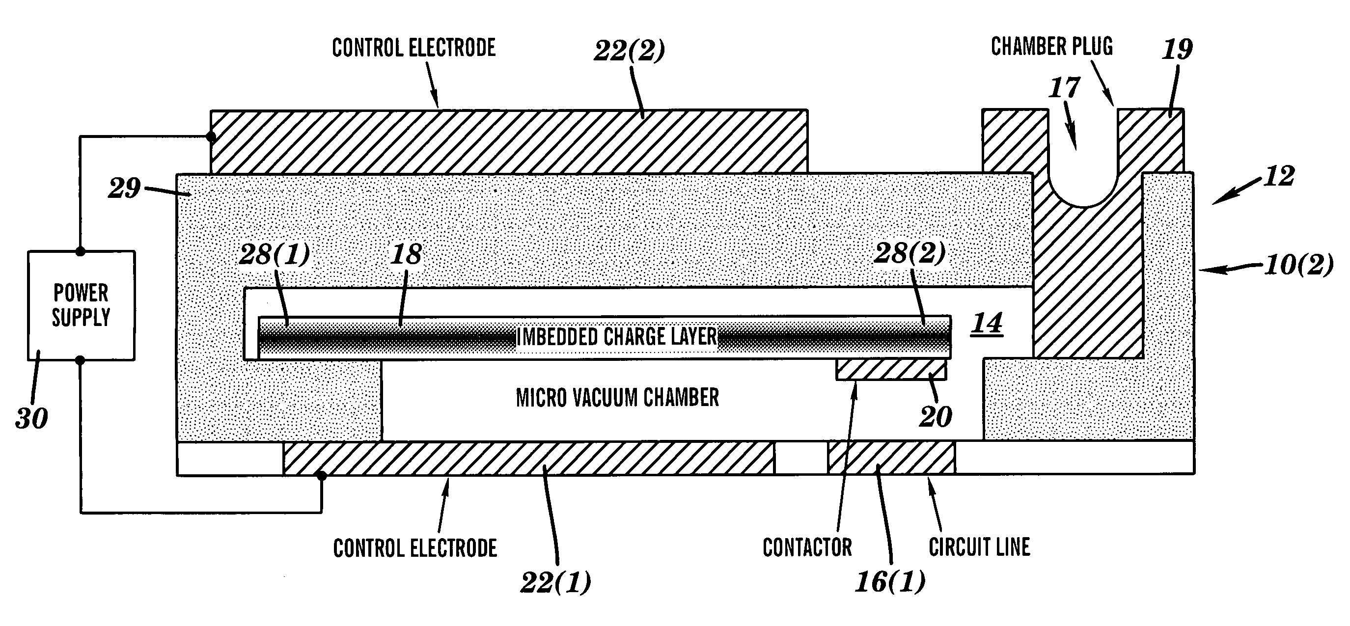
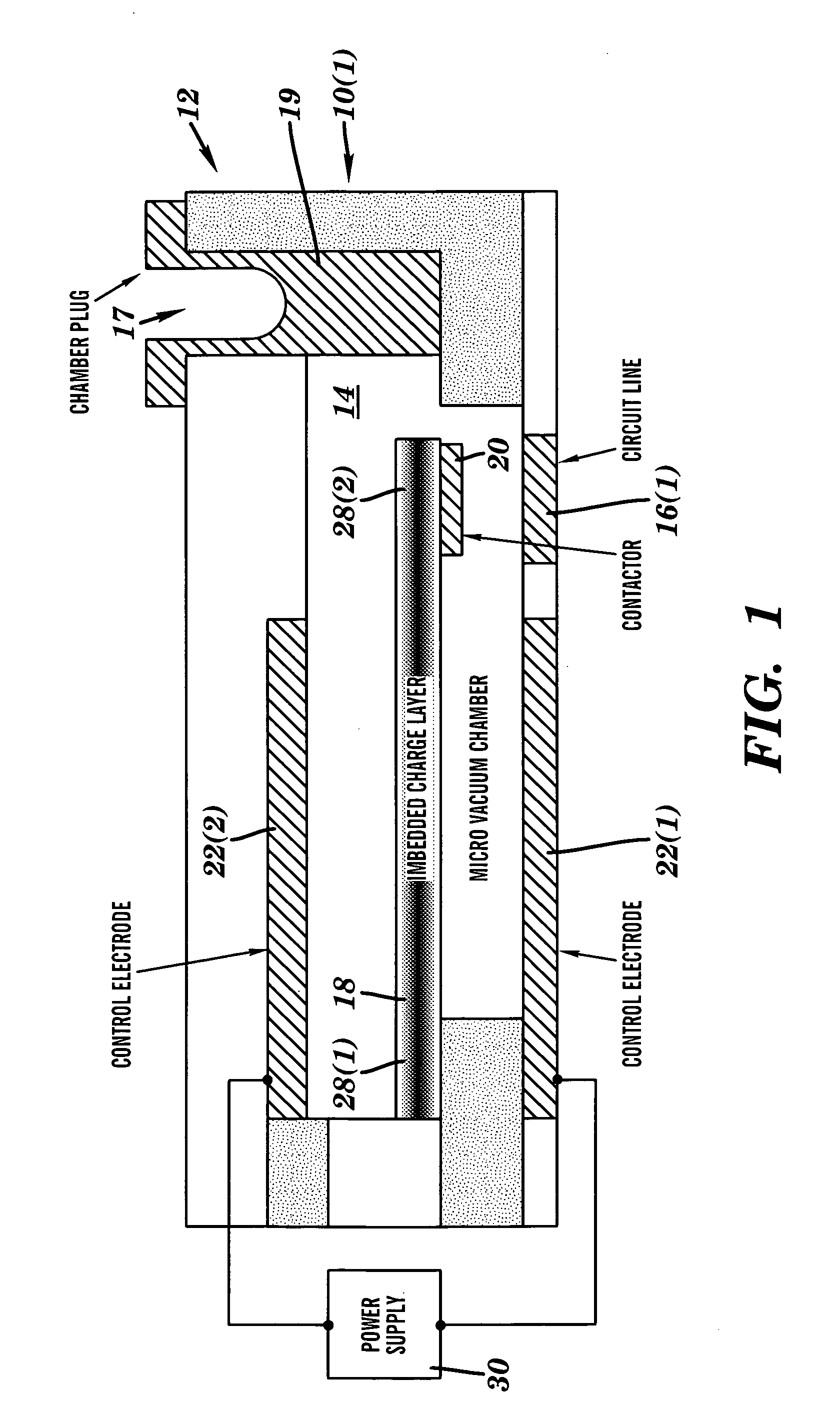
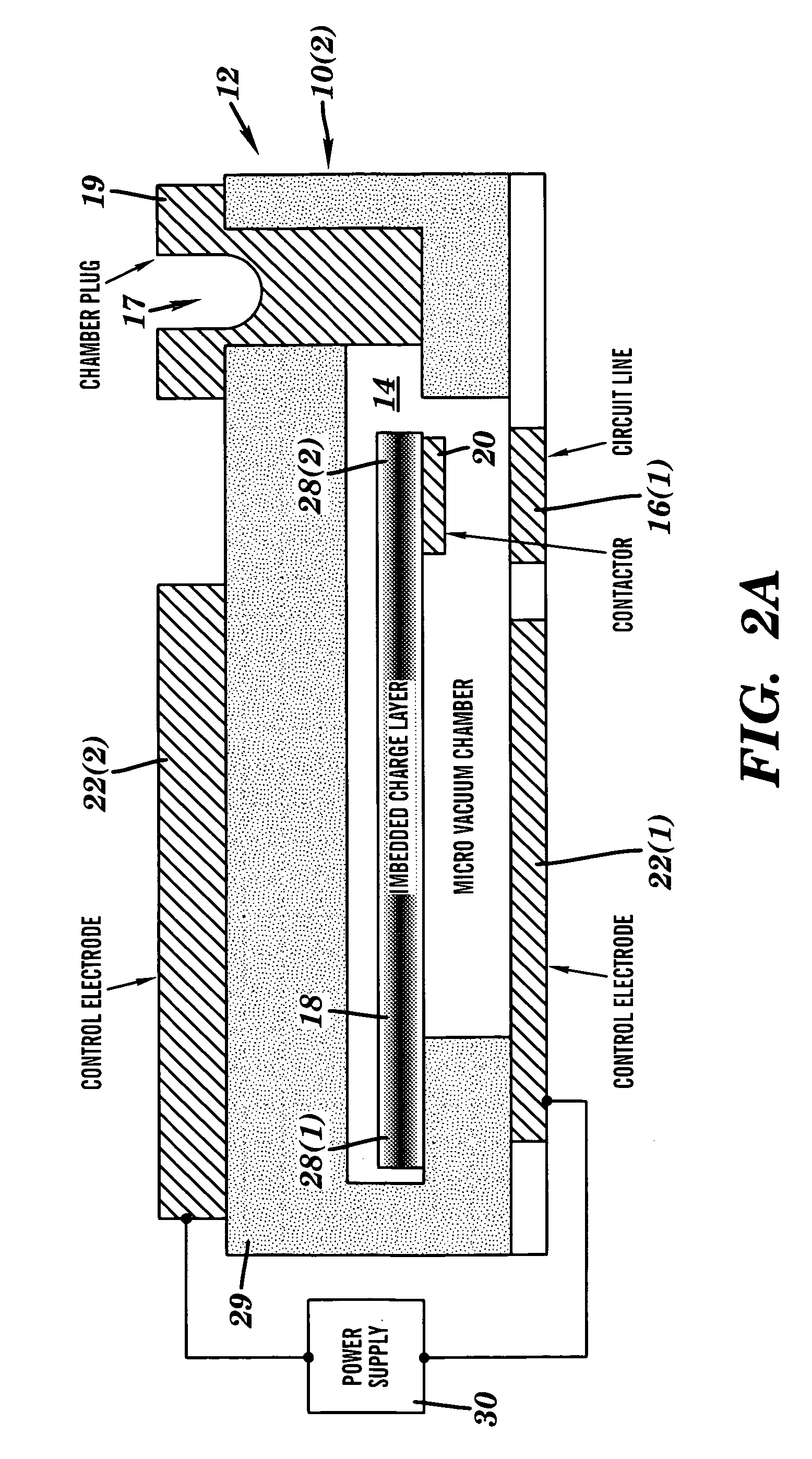
[0019]A switch 10(1) in accordance with at least one embodiment of the present invention is illustrated in FIG. 1. The switch 10(1) includes a switch housing 12 with a chamber 14, separated portions of a conductive line 16(1) and 16(2), a beam 18 with imbedded charge and a contactor 20, and control electrodes 22(1) and 22(2). The present invention provides a switch 10(1) that utilizes fixed static charge to apply attractive and repulsive forces for activation of the switch and to overcome stiction. This switch 10(1) has lower power requirements to operate, less parasitic capacitance, less mass, and faster switching speed or response than prior designs.

[0020]Referring more specifically to FIG. 1, the switch housing 12 defines a chamber 14 in which the switch 10(1) is located. The switch housing 12 is made of several layers of an insulating material, such as silicon dioxide, although other types of materials can be used and the switch housing 12 could comprise a single layer of materi...


PUM


Abstract

A micro-electro-mechanical switch includes at least one portion of a conductive line in the chamber, a beam with imbedded charge, and control electrodes. The beam has a conductive section which is positioned in substantial alignment with the at least one portion of the conductive line. The conductive section of the beam has an open position spaced away from the at least one portion of the conductive line and a closed position on the at least one portion of the conductive line. Each of the control electrodes is spaced away from an opposing side of the beam to control movement of the beam.

Description

[0001]The present invention claims the benefit of U.S. Provisional Patent Application Ser. No. 60 / 275,386, filed Mar. 13, 2001, which is hereby incorporated by reference in its entirety.FIELD OF THE INVENTION[0002]This invention relates generally to switches and, more particularly, to a micro-electro-mechanical switch (MEMS) and a method of using and making thereof.BACKGROUND OF THE INVENTION[0003]Micro-electro-mechanical switches are operated by an electrostatic charge, thermal, piezoelectric or other actuation mechanism. Application of an electrostatic charge to a control electrode in the MEMS causes the switch to close, while removal of the electrostatic charge on the control electrode, allowing the mechanical spring restoration force of the armature to open the switch. Although these MEMS switches work problems have prevented their more widespread use.[0004]For example, one problem with cantilever type MEMS is that they often freeze into a closed position due to a phenomenon kno...

Claims


Application Information

Patent Timeline
IPC IPC(8): H01H51/22H01H59/00
CPCH01H59/0009H01H2059/009
Inventor POTTER, MICHAEL D.
Owner ROCHESTER INSTITUTE OF TECHNOLOGY
Why Eureka
Try Eureka