Method and system for suppressing receiver audio regeneration

a receiver and audio technology, applied in the direction of transducer casings/cabinets/supports, electrical transducers, instruments, etc., can solve the problems of vibration in the handset device, internal acoustic pressure leakage to other compartments of the handset, and exacerbated problems

Active Publication Date: 2007-10-09
MOTOROLA SOLUTIONS INC
View PDF8 Cites 176 Cited by
  • Summary
  • Abstract
  • Description
  • Claims
  • Application Information

AI Technical Summary

Benefits of technology

[0009]The method can also include the steps of detecting speech activity on the audio signal, and, when detecting speech on the audio signal, determining whether the volume contour exceeds a predetermined threshold. For example, if no speech is detected on the audio signal, the method can include predicting the amount of pitch shifting. Accordingly, the level of pitch shifting applied can remain constant during a pause in the speech. Accordingly, the pitch-shifting of the audio signal can suppress the RF unit from entering unstable oscillation. For example, the pitch shifting can reduce the correlation between the high level audio acoustic output and the demodulated audio signal and suppress the handset from entering feedback and howling. The method can also include the steps of evaluating a gain margin and / or phase margin; and updating the predetermined threshold level based on the gain margin and / or phase margin. In one arrangement, the predetermined threshold sets an allowable gain headroom. For example, the gain margin and / or phase margin can describe the allowable extent of pitch shifting before unstable oscillation.
[0011]The pitch shifter can additionally include an analysis section that monitors a volume level of the audio signal, and when the volume level exceeds a predetermined volume level threshold, the pitch-shifter shifts the pitch of the audio signal by an amount that is a function of the volume level of the acoustic signal. In one arrangement, the pitch-shifter shifts the pitch of the audio signal by one of increasing and decreasing the pitch of the audio signal by an amount within a predetermined range. The system can also include an analysis section which can include a volume estimator block that estimates the acoustic signal volume for at least a portion of the time-based samples of the audio signal; and an envelope module that generates a volume contour of the acoustic signal based on the volume estimation. In one arrangement, the analysis section can further include a speech detector that can detect speech activity on the audio signal, and a threshold unit cooperatively connected to the speech detector that determines when the volume contour exceeds the predetermined threshold. For example, the speech detector can detect speech on the audio signal and the pitch-shifter can shift the pitch of the audio signal to suppress unstable oscillation in the RF unit.
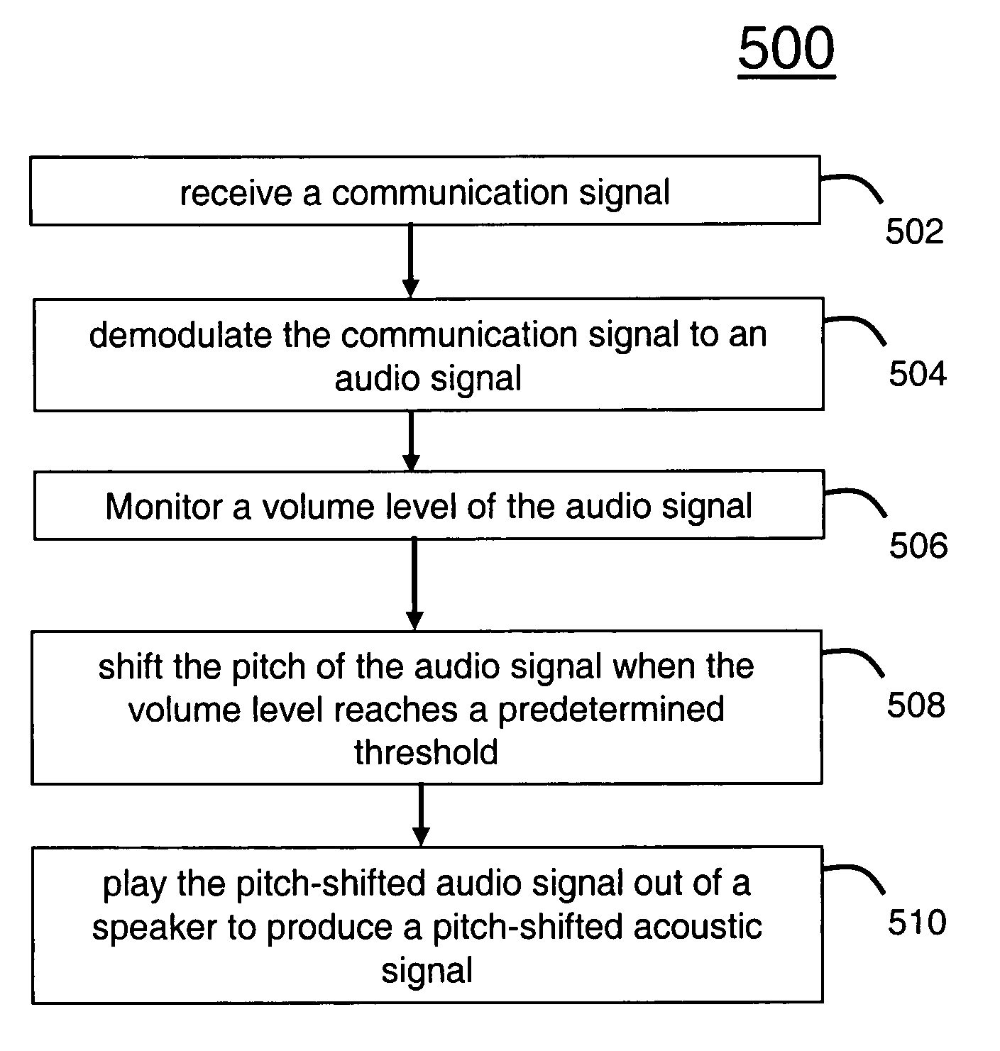
[0013]The embodiments of the present invention also concern a machine readable storage medium, having stored thereon a computer program having a plurality of code sections executable by a portable computing device. The code sections cause the portable computing device to perform the steps of at a RF unit receiving a communication signal, demodulating the communication signal into an audio signal, monitoring a volume level of the audio signal, shifting the pitch of the audio signal when the volume level reaches a predetermined threshold, wherein the amount of pitch-shifting is a function of the volume level, and playing the pitch-shifted audio signal out of a speaker to produce a pitch-shifted acoustic signal. At the RF unit, the code sections pitch-shift the audio signal to produce a pitch-shifted acoustic signal with signal properties suppressing regeneration of the acoustic signal onto the audio signal at the RF unit.

Problems solved by technology

The forceful movement of the diaphragm at high audio levels can also push air into and out of the handset creating pressure which accordingly produces vibrations in the handset device.
Also, when the handset is not properly enclosed or sealed, the internal acoustic pressure can leak to other compartments within the handset.
The problem is exacerbated when the speaker is in close proximity to the electrical board components.
All devices and components internal to the handset can be subject to these vibrations.
These vibrations can induce bending of component boards such as those that house the RF modulation circuitry.
This behavior is a feedback loop which can oscillate and go unstable when the signals become highly correlated, or in phase.
And, as handsets become smaller the microphonics problem can continue to increase.
Accordingly, a smaller handset can go unstable at high volumes which causes a howling effect as a result of receiver audio regeneration.
They rely on mechanical solutions that can not fully resolve the howling problem caused by the regenerative audio feedback.
However, this lowers the overall volume gain of the handset.
However, this reduces the overall loudness level which users expect from a high audio speaker handset.
In a public safety environment, or other high ambient noise condition, such restriction may not be acceptable.

Method used


Image

  • Method and system for suppressing receiver audio regeneration
  • Method and system for suppressing receiver audio regeneration
  • Method and system for suppressing receiver audio regeneration

Examples


Embodiment Construction

[0022]While the specification concludes with claims defining the features of the embodiments in accordance with the invention that are regarded as novel, it is believed that the embodiments will be better understood from a consideration of the following description in conjunction with the drawing figures, in which like reference numerals are carried forward.

[0023]As required, detailed embodiments are disclosed herein; however, it is to be understood that the disclosed embodiments can be embodied in various forms. Therefore, specific structural and functional details disclosed herein are not to be interpreted as limiting, but merely as a basis for the claims and as a representative basis for teaching one skilled in the art to variously employ the embodiments in virtually any appropriately detailed structure. Further, the terms and phrases used herein are not intended to be limiting but rather to provide an understandable description of the invention.

[0024]The terms a or an, as used h...


PUM


Abstract

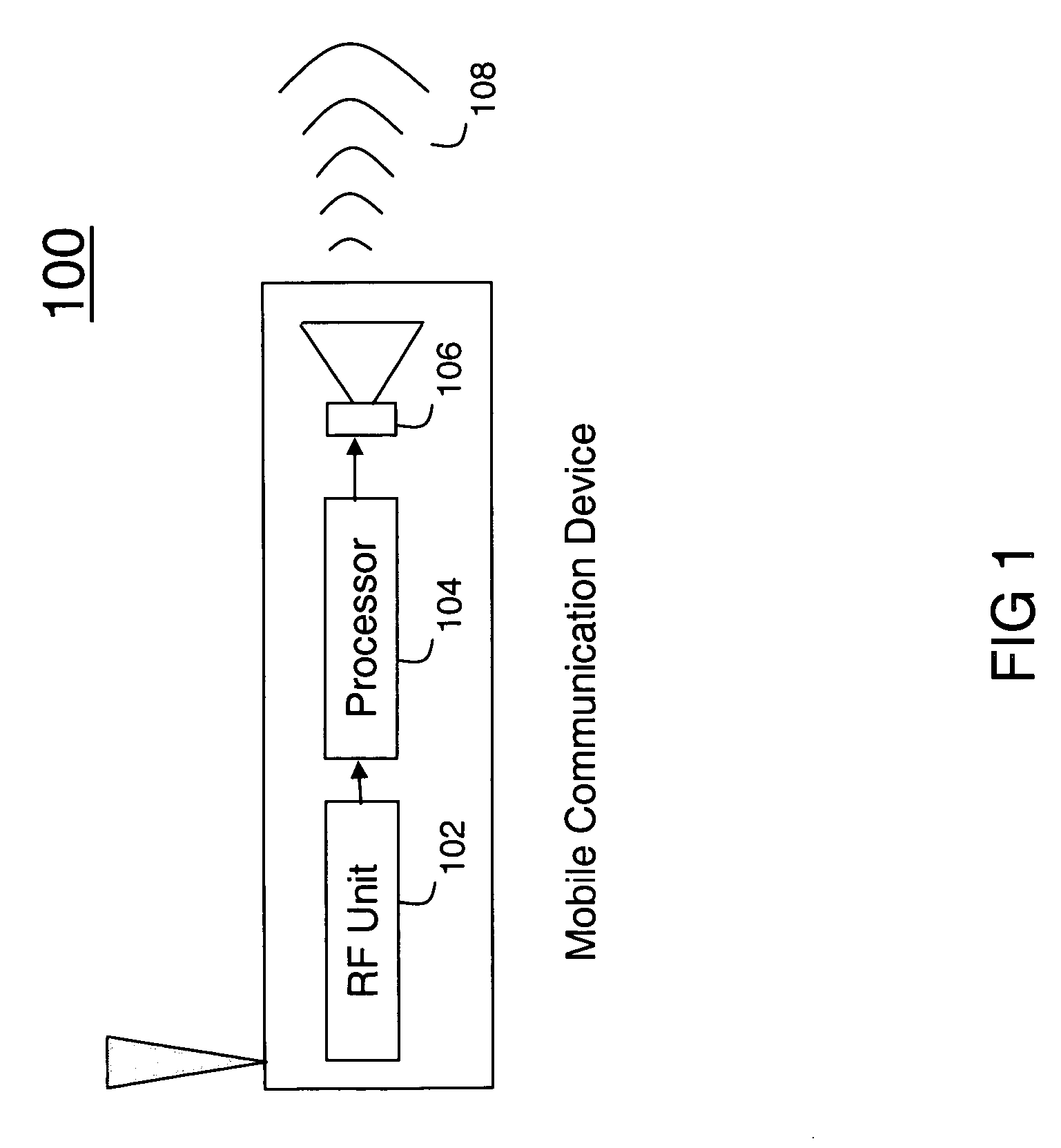
The invention concerns a method (500) and system (100) for suppressing receiver audio regeneration. The method (500) includes the steps of receiving a communication signal (502), at a Radio Frequency (RF) unit (102), demodulating the communication signal to an audio signal (504), monitoring a volume level of the audio signal (506), and shifting the pitch of the audio signal when the volume level reaches a predetermined threshold (508), and playing the pitch-shifted audio signal out of a speaker to produce a pitch-shifted acoustic signal (510). The method can shift the pitch of the audio signal to produce a pitch-shifted acoustic signal with signal properties suppressing regeneration of the acoustic signal onto the audio signal at the RF unit. The amount of pitch-shifting can be a function of the volume level.

Description

FIELD OF INVENTION[0001]This invention relates in general to methods and systems that transmit and receive audio and more particularly, to high audio speaker phone systems.BACKGROUND[0002]In recent years, portable electronic devices, such as cellular telephones and personal digital assistants, have become commonplace. Many of these devices include a Radio Frequency (RF) modulator section. The RF modulator can reside within a transmitter unit on a portable device to modulate base-band signals to communication signal frequencies for transmission whereby the communication signals are broadcast to other portable units with a RF modulator at the receiver unit capable of demodulating the signals back down to base-band. The base-band signals can be decoded into an audio signal and broadcast through a speaker to a user of the receiving portable electronic device.[0003]Many of the portable handset devices include a high-audio speaker to play the audio signal at higher volume levels. A power ...

Claims


Application Information

Patent Timeline
Patent Type & Authority Patents(United States)
IPC IPC(8): G10L11/04G10L21/00G10L25/90
CPCH04R3/02G10L21/02G10L21/013
Inventor PAVLOV, PETER M.MCINTOSH, JASON D.JOHNSON, GRAEME P.
Owner MOTOROLA SOLUTIONS INC
Why Eureka
Try Eureka