Turbine cement/water mixer for concrete production

a technology of water mixer and cement mixer, which is applied in the direction of clay preparation apparatus, rotary stirring mixer, transportation and packaging, etc., can solve the problems of inability to fully hydrate cement in such operations, the unit cost of mobile production of concrete is higher than the cost of conventional batch production of concrete, etc., to enhance the ability of the resultant concrete mix, increase the air content, and the effect of durable construction

Inactive Publication Date: 2007-10-16
ZIMMERMAN INDS
View PDF20 Cites 16 Cited by
  • Summary
  • Abstract
  • Description
  • Claims
  • Application Information

AI Technical Summary

Benefits of technology

[0023]It is a further advantage of this invention that the pre-mixing of cement and water before being added to aggregates will eliminate the dispersion of cement dust into the atmosphere.
[0024]It is still a further advantage of this invention that the increased air content incorporated into the pre-mixed water and cement by the high-speed turbine mixer enhances the ability of the resultant concrete mix to be pumped and placed on site.
[0025]It is yet another object of this invention to provide a method of creating a more homogeneous and fluid concrete mix through the high speed pre-mixing of water and cement before being added to aggregates.
[0026]It is a further object of this invention to provide a turbine mixer for the pre-mixing of water and cement that is durable in construction, inexpensive of manufacture, carefree of maintenance, facile in assemblage, and simple and effective in use.
[0027]It is still a further object of this invention to provide an improved method of making concrete that provides a higher quality finished concrete product th

Problems solved by technology

A mere repositioning of the mixing auger apparatus to the front of the truck to enable the forward discharge of the mixed concrete forwardly thereof is not a simple design choice as the operator's cab of the truck prevents the relocation of the mixing auger apparatus

Method used


Image

  • Turbine cement/water mixer for concrete production
  • Turbine cement/water mixer for concrete production
  • Turbine cement/water mixer for concrete production

Examples


Embodiment Construction

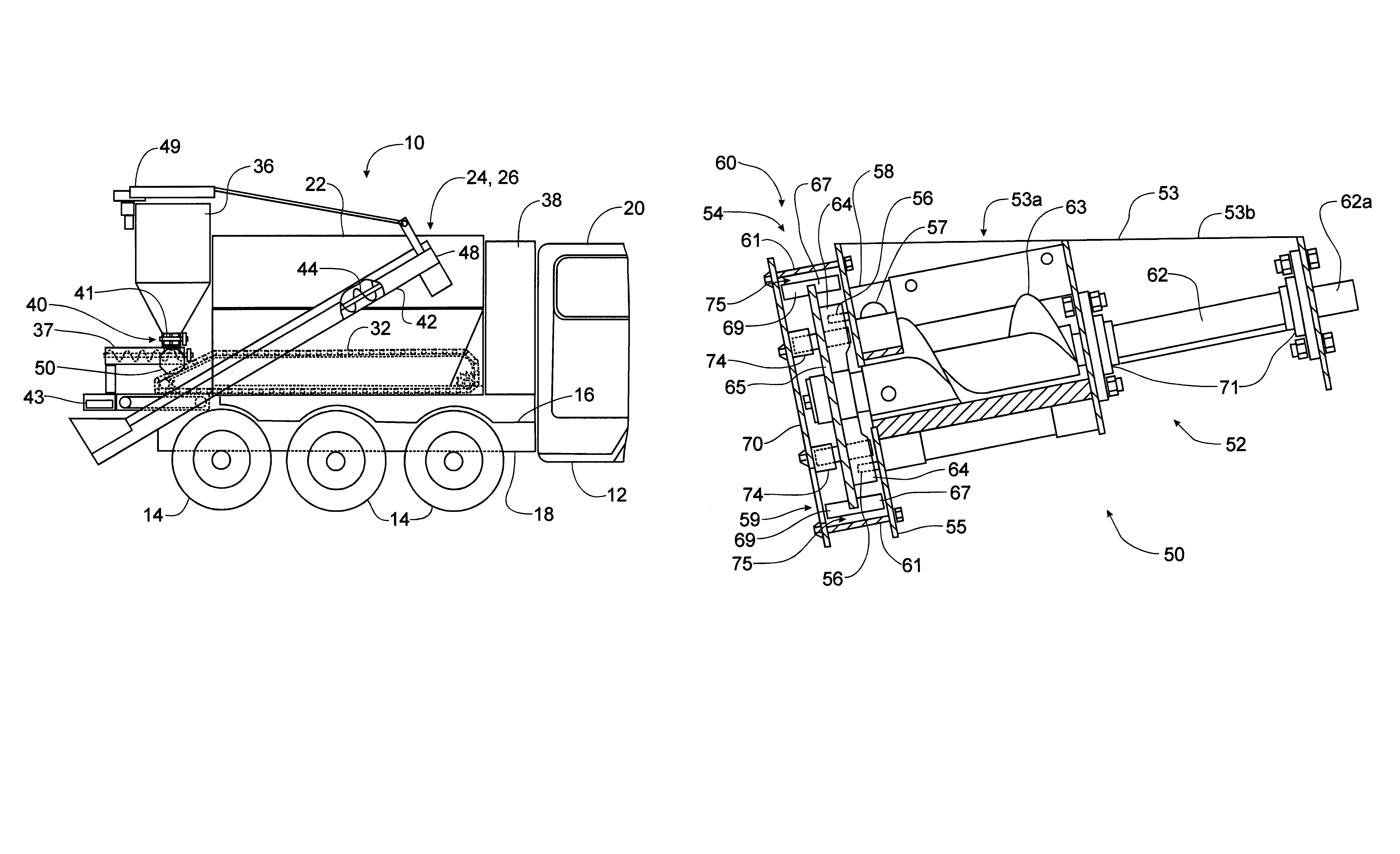
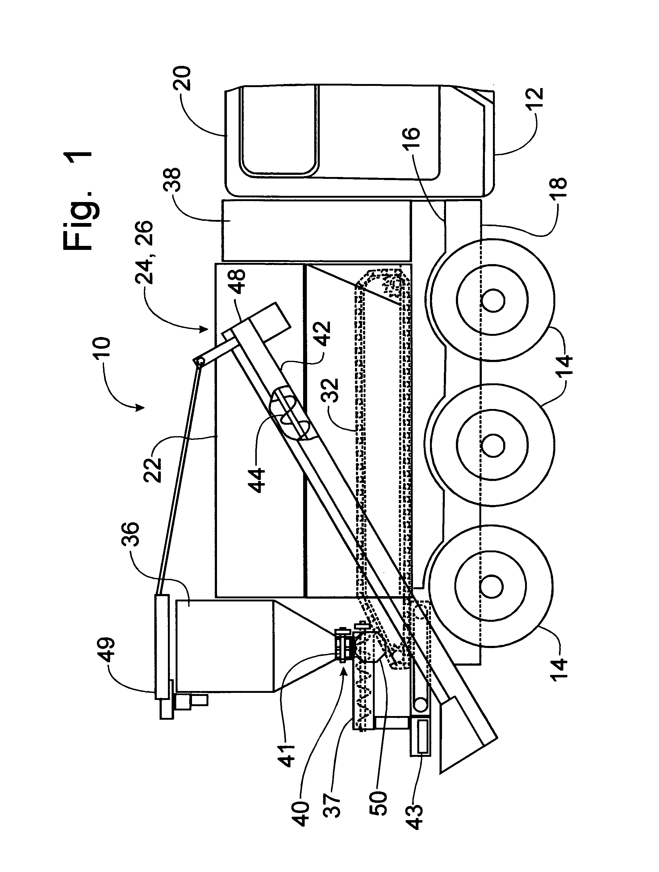
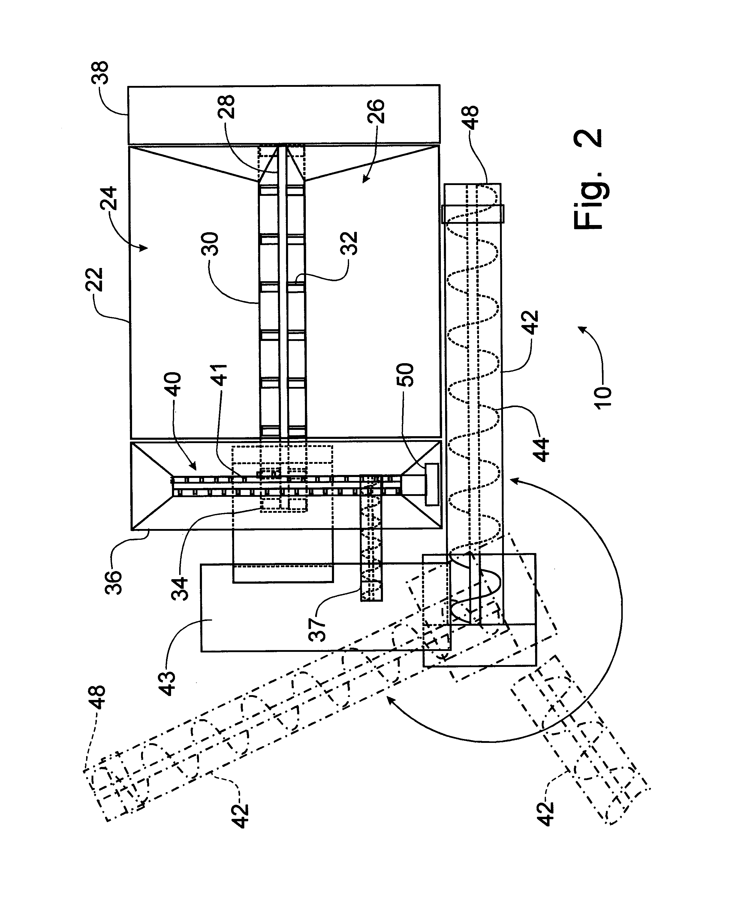
[0042]Referring now to FIGS. 1-3, a representative mobile concrete mixer can best be seen. Left and right references are used as a matter of convenience and are determined by standing at the rear of the concrete mixer and facing the forward end, where the operator's cab is positioned, in the normal direction of travel. While the mobile concrete production system is shown and described in the drawings to explain the nature of the invention, one of ordinary skill in the art will readily understand that the principles of the instant invention are not limited to the mobile concrete production system and will be readily applicable to conventional ready mix, or batch operations as well. The turbine mixer shown in the drawings and described below will be applicable to any form of concrete production. Accordingly, a representative mobile concrete production system is shown in the drawings.

[0043]The mobile concrete production mixer 10 is provided with a chassis 12, made mobile by tandemly ar...


PUM

PropertyMeasurementUnit
Flow rateaaaaaaaaaa
Diameteraaaaaaaaaa
Speedaaaaaaaaaa

Abstract

A high-speed turbine mixer combines water and cement into a pre-mixed cement paste that is added to aggregates to create a concrete mix. The turbine mixer includes a housing that cooperates with an auger to move dry cement into a mixing chamber where water is added. A mixing plate rotates at high speed to break up water and cement into small particles that enhances the hydration of the cement and increases the air content in the resultant cement paste. The cement paste is then conveyed to a mixing auger to be combined with aggregates to create a concrete mix. The mixing plate divides the mixing chamber to force the mixing water and cement particles to pass through a circumferential annular opening past agitating fins. Admixtures can be added to the cement as a powder or to the water as a liquid for incorporation into the cement paste.

Description

CROSS-REFERENCE TO RELATED APPLICATIONS[0001]This application claims domestic priority of U.S. Provisional Patent Application Ser. No. 60 / 450,570, filed Feb. 28, 2003, the contents of which are incorporated herein by reference.BACKGROUND OF THE INVENTION[0002]The present invention relates generally to an apparatus to mix concrete and, more particularly, to a turbine cement / water mixing apparatus for premixing a cement slurry for use in the production of concrete.[0003]Concrete trucks, such as is described in U.S. Pat. No. 3,310,293, issued to Harold M. Zimmerman on Mar. 21, 1967, and U.S. Patent No. 4,406,548, issued to Paul M. Haws on Sep. 27, 1983, carry supplies, such as aggregate, cement and water, in discrete hoppers from which the supplies are drawn in predetermined ratios to be deposited in a mixing auger apparatus where the combined supplies are mixed and turned into concrete to be discharged from the mixing auger externally of the concrete truck. This mixing auger apparatus...

Claims


Application Information

Patent Timeline
IPC IPC(8): B28C5/08B01F7/10B28C5/12B01F27/73
CPCB01F7/00241B28C9/0463B28C5/1238B01F15/0251B01F27/111B01F35/71775
Inventor ZIMMERMAN, HAROLD M.
Owner ZIMMERMAN INDS
Why Eureka
Try Eureka