Use of ellipsometry and surface plasmon resonance in monitoring thin film deposition or removal from a substrate surface

a technology of surface plasmon resonance and surface plasmon resonance, which is applied in the direction of optical radiation measurement, instruments, measurement devices, etc., can solve the problems of not always optimal and the delta cannot be determined

Inactive Publication Date: 2007-10-16
J A WOOLLAM CO
View PDF2 Cites 7 Cited by
  • Summary
  • Abstract
  • Description
  • Claims
  • Application Information

AI Technical Summary

Benefits of technology

[0017]The present invention recognizes that while Ellipsometry provides sensitivity to layers of material on the order of a nonometer, additional sensitivity to even thinner layers would be of benefit. The present invention provides for the use of the Surface Plasmon Resonance (SPR) effect in the monitoring of deposition or etching of thin layers of material, either independently or in symbiotic combination with practice of conventional ellipsometry. It is noted that the SPR technique requires that P-Polarized electromagnetic radiation be applied, whereas conventional ellipsometry can utilize any polarization orientation. The present invention then provides for application of P-Polarized and Non-P-Polarized electromagnetic radiation, simultaneously or sequentially, to a sample during deposition or removal of one or more thin films on a surface thereof.

Problems solved by technology

They can read PSI and DELTA of a Material System over a full Range of Degrees with the only limitation being that if PSI becomes essentially zero (0.0), DELTA can not then be determined as there is not sufficient PSI Polar Vector Length to form the angle between the PSI Vector and an “X” axis.
Finally, while ellipsometric DELTA is generally more sensitive to layer thickness, and ellipsometric PSI is generally more sensitive to surface roughness and grading etc., it does occur that in some cases ellipsometric PSI provides better sensitivity to surface change than does ellipsometric DELTA. The foregoing recital focused on primary reference to ellipsometric DELTA, however, such is not always optimum.

Method used


Image

  • Use of ellipsometry and surface plasmon resonance in monitoring thin film deposition or removal from a substrate surface
  • Use of ellipsometry and surface plasmon resonance in monitoring thin film deposition or removal from a substrate surface
  • Use of ellipsometry and surface plasmon resonance in monitoring thin film deposition or removal from a substrate surface

Examples


Embodiment Construction

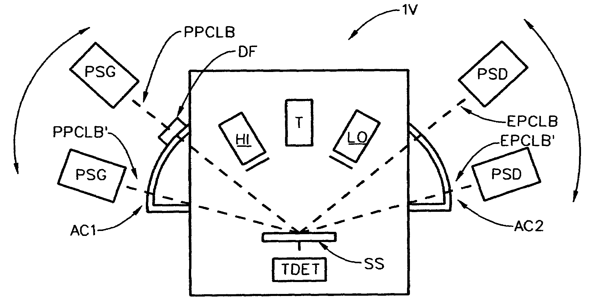
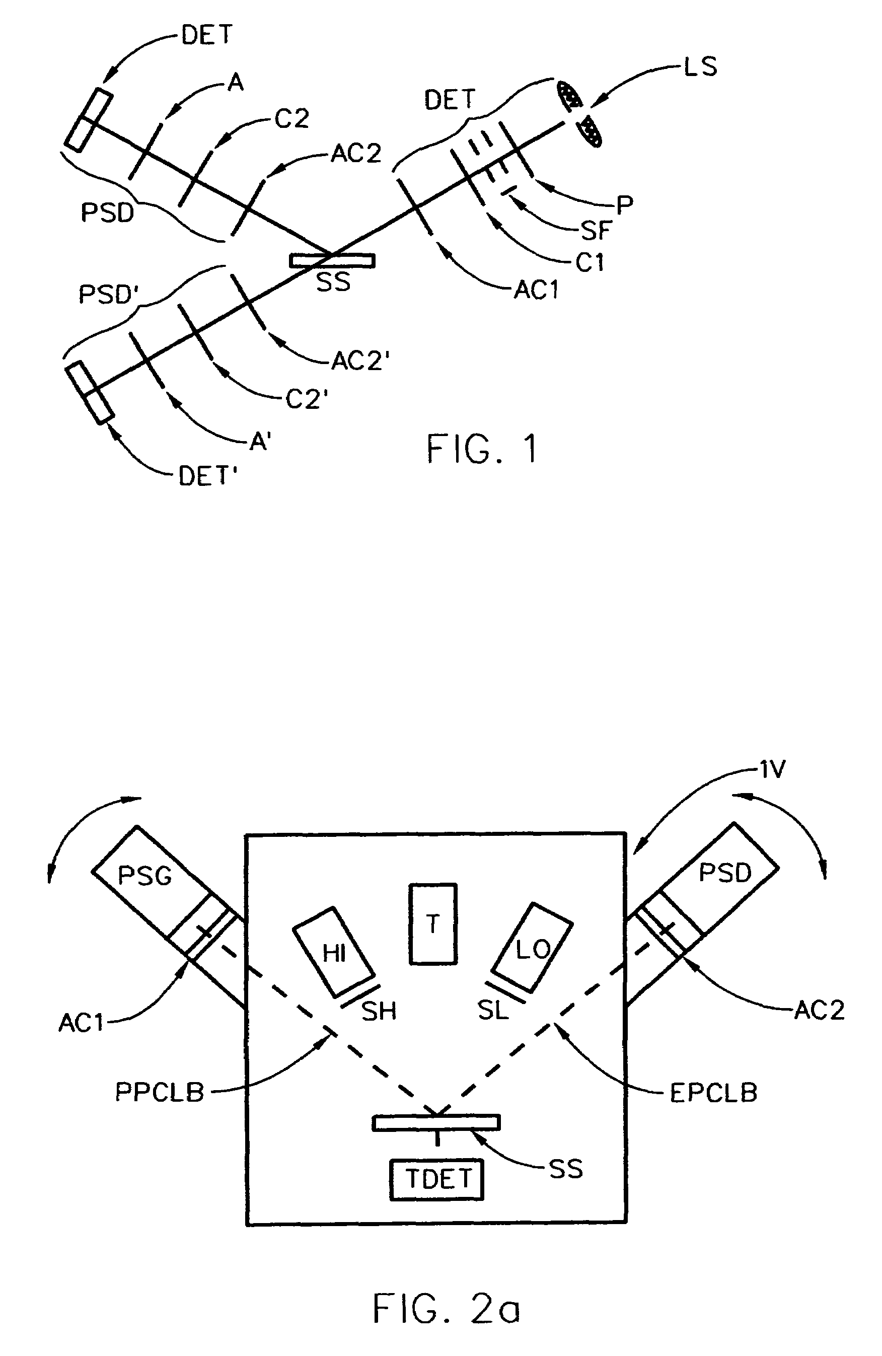
[0095]To begin, for general insight it should be appreciated that FIG. 1 demonstrates an ellipsometer system which can be applied to investigate a substrate sytsem (SS). Shown for both Reflection and Transmission are, sequentially:[0096]a. a Source of a beam electromagnetic radiation (LS);[0097]b. a Polarizer element (P);[0098]c. optionally a compensator element (C1);[0099]d. (additional element(s)) (AC1);[0100]e. a substrate system (SS);[0101]f. (additional element(s)) (AC2);[0102]g. optionally a compensator element (C2);[0103]h. an Analyzer element (A); and[0104]i. a Detector System (DET).

[0105]It is noted that the elements identified as (LS), (P) and (C1) can be considered to form, as a group, a Polarization State Generator (PSG), and the components (C2), (A) and (DET) can be considered, as a group, to form a Polarization State Detector (PSD). It is to be understood that the d. and f. “additional elements”, (AC1) and (AC2), can be considered as being, for the purposes of the disc...


PUM


Abstract

Improved methodology for monitoring deposition or removal of material to or from a process and/or wittness substrate which demonstrates a negative e1 at some wavelength. The method involves detection of changes in P-polarized electromagnetism ellipsometric DELTA at SPR Resonance Angle-of-Incidence (AOI) to monitor deposition of and/or removal of minute amounts of materials onto, or from, said process and/or witness substrate. The methodology can optionally monitor ellipsometric PSI, and involves simultaneously or sequentially applying non-P-polarized electromagnetism at the same angle of incidence, or electromagnetic radiation of any polarization at a different angle-of-incidence and wavelength to the process or wittness substrate and application of conventional ellipsometric analysis.

Description

[0001]This application is a Continuation-In-Part of application Ser. No. 10 / 238,241 Filed Sep. 10, 2002 now U.S. Pat. No. 6,937,341, and of Ser. No. 09 / 756,515 Filed Jan. 9, 2001 now U.S. Pat. No. 6,455,853, and therevia Claims benefit of Provisional Application Ser. No. 60 / 183,977 Filed Feb. 22, 2000. This Application is further a Continuation-In-Part of application Ser. No. 09 / 162,217, now U.S. Pat. No. 6,034,777, Filed Sep. 29, 1998 via Pending application Ser. Nos. 10 / 829,620, Filed Apr. 22, 2004, and 10 / 925,333 Filed Aug. 24, 2004, and 09 / 419,794, Filed Oct. 18, 1999 (now U.S. Pat. No. 6,549,282), which was a CIP of said 777 Patent.[0002]This Application directly Claims benefit from Provisional Applications 06 / 609,339, Filed Sep. 14, 2004; 60 / 598,456, Filed Aug. 3, 2004, and 60 / 530,416, Filed Dec. 17, 2003.TECHNICAL FIELD[0003]The disclosed invention relates to methodology for monitoring thin film deposition or removal from the surface of a substrate, and more particularly to m...

Claims


Application Information

Patent Timeline
Patent Type & Authority Patents(United States)
IPC IPC(8): G01J4/00
CPCG01N21/211G01N21/553G01N2021/213
Inventor WOOLLAM, JOHN A.JOHS, BLAINE D.TIWALD, THOMAS E.LIPHARDT, MARTIN M.WELCH, JAMES D.
Owner J A WOOLLAM CO
Why Eureka
Try Eureka