
Method of manufacturing a suspension using coining

a manufacturing method and technology of suspension, applied in the direction of instruments, record information storage, support for heads, etc., can solve the problems of excessive noise, excessive wear, and excessive tolerance of photo-chemical etching in the vertical direction, so as to minimize the variation of vertical stiffness and gram loading, and the effect of reducing the impact of performan

Inactive Publication Date: 2007-10-16
HITACHI GLOBAL STORAGE TECH NETHERLANDS BV
View PDF25 Cites 0 Cited by
  • Summary
  • Abstract
  • Description
  • Claims
  • Application Information

AI Technical Summary

Benefits of technology

[0012]Treatment of the pockets preferably includes applying a compressive force on the pockets in excess of a bearing strength of the material used to form the suspension member. The minimal pocket depth tolerances provided by the treatment are preferably equal to or better than the thickness tolerances associated with conventionally rolled material. In this way, variations in vertical stiffness and gram loading will be minimized. Variations in dynamic frequency characteristics will also be minimized. Any excess material in the pockets will flow in a controlled desired direction that has the least impact on performance, namely in the length and width directions and not in the thickness direction, which is maintained. The treatment will also preferably cold work the suspension member material and any strength lost as a result of previous processing, such as etching, will be partially or wholly restored.

Problems solved by technology

Excessive gain caused by resonance at critical dynamic frequencies can induce unwanted torsion, sway and bending, all of which can contribute to track misalignment problems, excessive noise, and undue wear.
Notwithstanding its advantages, photo-chemical etching generates excessive tolerances in the vertical direction (e.g., 2-4 times that of rolled material).
This can produce unacceptable variations in gram loading and torsional dynamic characteristics.
The problem is that the tolerances required to produce satisfactory pocket depth uniformity are at the process limits of photo-chemical etching.
An additional problem associated with partial etching is its tendency to relieve the internal stresses that are locked into the steel material during the cold rolling reduction process.
This stress relief may cause an unacceptable lowering of load beam strength in the etched areas.

Method used


Image

  • Method of manufacturing a suspension using coining
  • Method of manufacturing a suspension using coining
  • Method of manufacturing a suspension using coining

Examples


Embodiment Construction

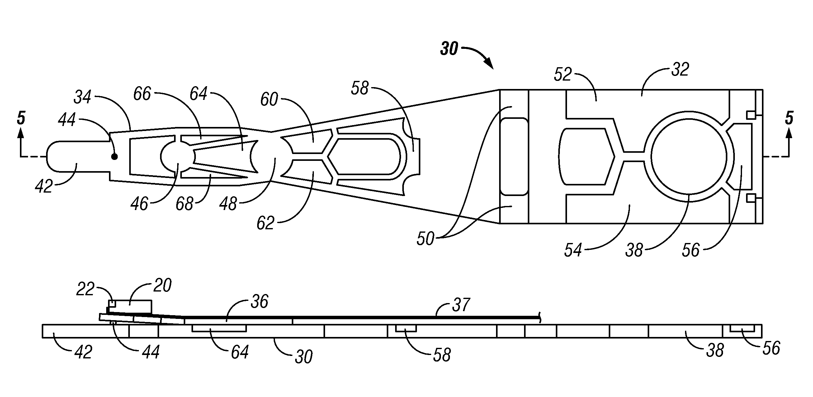
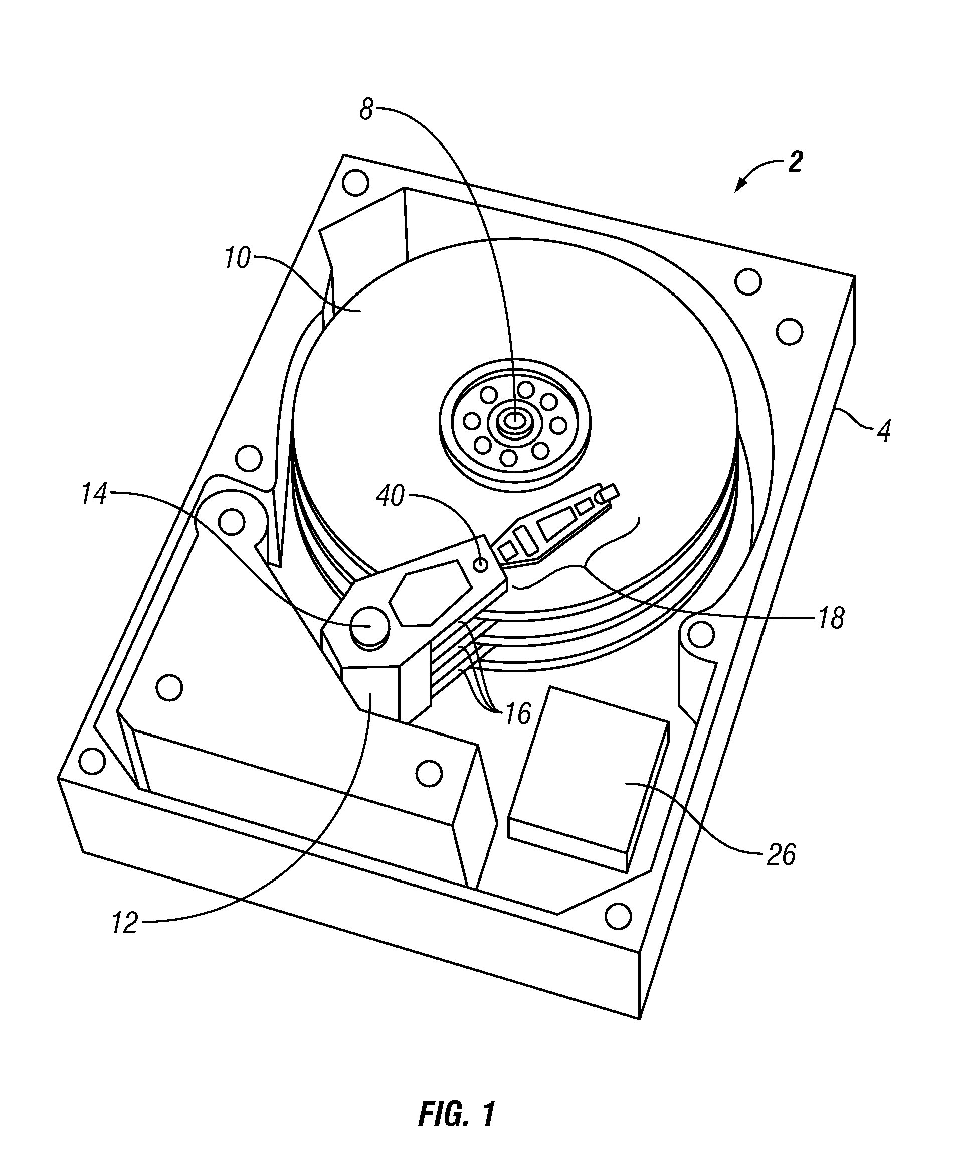
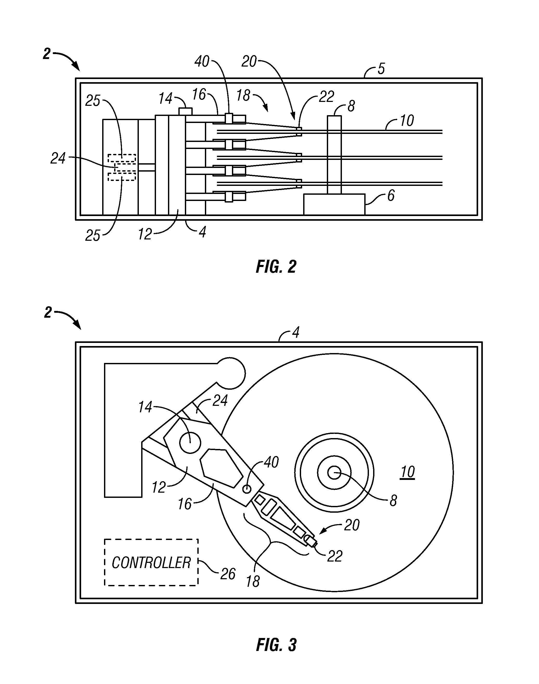
[0028]Turning now to the figures, wherein like reference numerals represent like elements in all of the several views, FIGS. 1-3 illustrate a disk drive 2 having a suspension load beam (described below) that has been manufactured in accordance with the invention. The disk drive 2 conventionally includes a base casting 4 made from cast aluminum or other suitable material. A cover 5 is removably mounted thereto via a hermetic seal (not shown). The base casting 4 mounts a conventional spindle drive motor 6 having an associated drive spindle 8. The drive spindle 8 carries a stacked array of disks 10 for high speed rotation therewith. The disks 10 are made from a suitable material of a type usually found in magnetic disk drive assemblies. In particular, the disks 10 may be formed from an aluminum or glass substrate with appropriate coatings being applied thereto such that at least one, and preferably both, of the upper and lower surfaces of the disks are magnetically encodable and aerody...


PUM

PropertyMeasurementUnit
lengthaaaaaaaaaa
sizeaaaaaaaaaa
lengthaaaaaaaaaa

Abstract

A method of manufacturing a suspension member designed to carry a slider and read / write head elements in a magnetic data storage device. The method includes forming the suspension member into a desired length and width configuration with a nominal thickness dimension. One or more pockets are formed in one or both surfaces of the suspension member. The pockets are treated by way of punch-coining or roll-coining to minimize pocket depth tolerances and introduce hardness and strength into surface areas of said pockets.

Description

BACKGROUND OF THE INVENTION[0001]1. Field of the Invention[0002]The present invention relates to data storage apparatus for magnetically read and writing information on data storage media. More particularly, the invention concerns the fabrication of suspension assemblies designed to carry read / write heads in magnetic disk drive storage devices.[0003]2. Description of the Prior Art[0004]By way of background, a read / write head of a magnetic disk drive storage device (“disk drive”) is typically incorporated on an air bearing slider that is designed to fly closely above the surface of a spinning magnetic disk medium during drive operation. The slider is mounted at the end of a suspension assembly that in turn is cantilevered from the arm of a pivotable actuator. When energized, the actuator sweeps the suspension across the spinning disk surface, allowing the read / write head to read and write data in a series of concentric tracks.[0005]The suspension of a conventional disk drive typicall...

Claims


Application Information

Patent Timeline
Patent Type & Authority Patents(United States)
IPC IPC(8): G11B5/48G11B5/127
CPCG11B5/4833Y10T29/49032
Inventor ARYA, SATYA PRAKASH
Owner HITACHI GLOBAL STORAGE TECH NETHERLANDS BV
Learn More