Remaining toner detection apparatus and image forming apparatus provided with same

a technology of toner detection apparatus and image forming apparatus, which is applied in the direction of electrographic process apparatus, instruments, optics, etc., can solve the problems of difficult toner indentations translucent windows, and achieve the effect of narrowing the width of the toner cartridg

Active Publication Date: 2007-10-16
SHARP KK
View PDF7 Cites 5 Cited by
  • Summary
  • Abstract
  • Description
  • Claims
  • Application Information

AI Technical Summary

Benefits of technology

[0015]Furthermore, since the indentations are arranged vertically, even when toner drops from above, the upper side indentation acts as a roof so that the toner is prevented from directly dropping on the space between the indentations, and it is difficult for the translucent windows of the indentations become smeared. In this way, it is possible to always accurately determine the remaining toner. Furthermore, since toner does not drop directly on the space between the indentations, the level of toner is kept stable in this space and it is possible to carry out very accurate determinations of the remaining toner.
[0017]In this case, it is possible to remove smearing from the translucent windows of the indentations and always accurately determine the remaining toner.
[0025]In this case, since the sweeping member is film with flexibility, when there is sufficient toner, the sweeping member is immersed, receives large resistance and bends in shape, and when there is little toner, the shape of the member recovers. Using this, when there is sufficient toner, the sweeping member is hindered from approaching the translucent windows of the indentations due to the shape change of the sweeping member, thus preventing the occurrence of abrasions to the surfaces of the translucent windows of the indentations due to sliding contact with the sweeping member. And when there is little toner, the sweeping member slides in contact with surfaces of the translucent windows of the indentations due to the recover of shape of the sweeping member, and the surfaces of the translucent windows of the indentations can be swept by the sliding contact with the sweeping member. Furthermore, if the sweeping member is a flexible film, even when the sweeping member slides in contact with the surfaces of the translucent windows of the indentations, these surfaces of the translucent windows are only lightly rubbed, and it is difficult to abrade the surfaces of the translucent windows. Furthermore, if the sweeping member is a flexible film, there is little friction between the sweeping member and the surfaces of the translucent windows of the indentations. For this reason, if the sweeping member is made to operate together with the agitation movement of the agitator member, it is possible to suppress increases to the load applied to the agitator member and there is no unevenness in the agitation movement of the agitator member.
[0027]In this case, since the depth of the toner cartridge is set shorter than the depth of the developing device in an image forming apparatus, it is easy to make uniform the toner in the toner cartridge using agitation of the agitator member, and this reduces deviation in the toner, thus making it possible to carry out accurate determination of the remaining toner. Furthermore, since the height of the toner cartridge is set longer than the depth of the toner cartridge, the capacity of the toner cartridge can be maintained. It should be noted that, when comparing the depth of the toner cartridge and the depth of the developing device, it is preferable for the depth of the toner cartridge to be sufficiently shorter than the depth of the developing device.
[0033]According to the present invention, regardless of the arrangement state of the light-emitting face of the light-emitting element and the light-receiving face of the light-receiving element, the flexible film is made to pass through the vicinity of the light-emitting face and the light-receiving face such that the light-emitting face and the light-receiving face are swept by the flexible film. The flexible film lightly rubs the light-emitting face and the light-receiving face and removes smearing from the light-emitting face and the light-receiving face without causing abrasion to the light-emitting face and the light-receiving face.
[0035]In the present invention, since is it possible to bring the toner cartridges close to the front door, it is also possible to achieve miniaturization of an image forming apparatus. In particular, if a height h of the toner cartridge is set longer than a depth t of the toner cartridge and thus making the width of the toner cartridge even narrower, the toner cartridge can be miniaturized such that the image forming apparatus can also be further miniaturized.

Problems solved by technology

Furthermore, since the indentations are arranged vertically, even when toner drops from above, the upper side indentation acts as a roof so that the toner is prevented from directly dropping on the space between the indentations, and it is difficult for the translucent windows of the indentations become smeared.

Method used


Image

  • Remaining toner detection apparatus and image forming apparatus provided with same
  • Remaining toner detection apparatus and image forming apparatus provided with same
  • Remaining toner detection apparatus and image forming apparatus provided with same

Examples


example 1

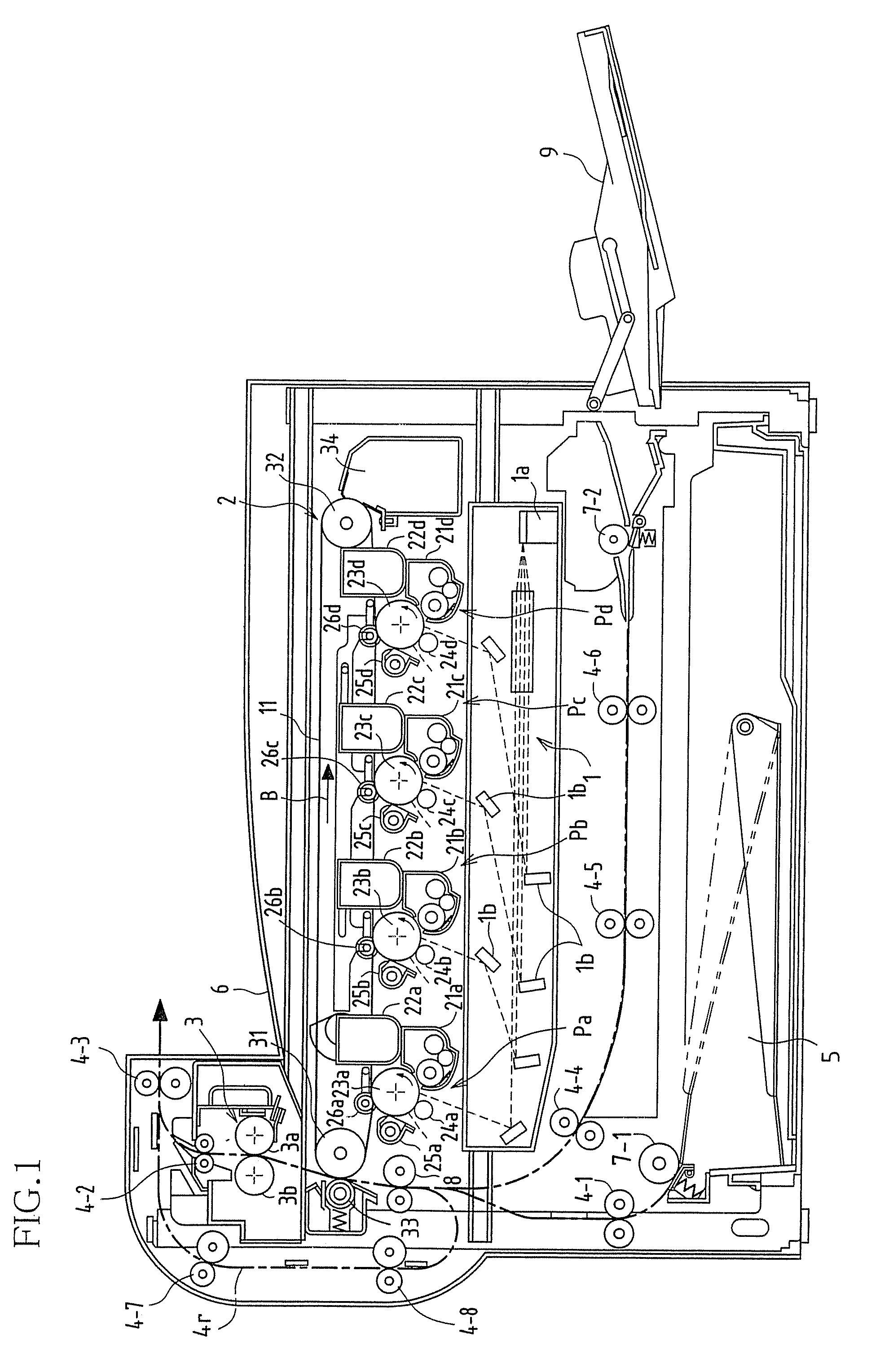
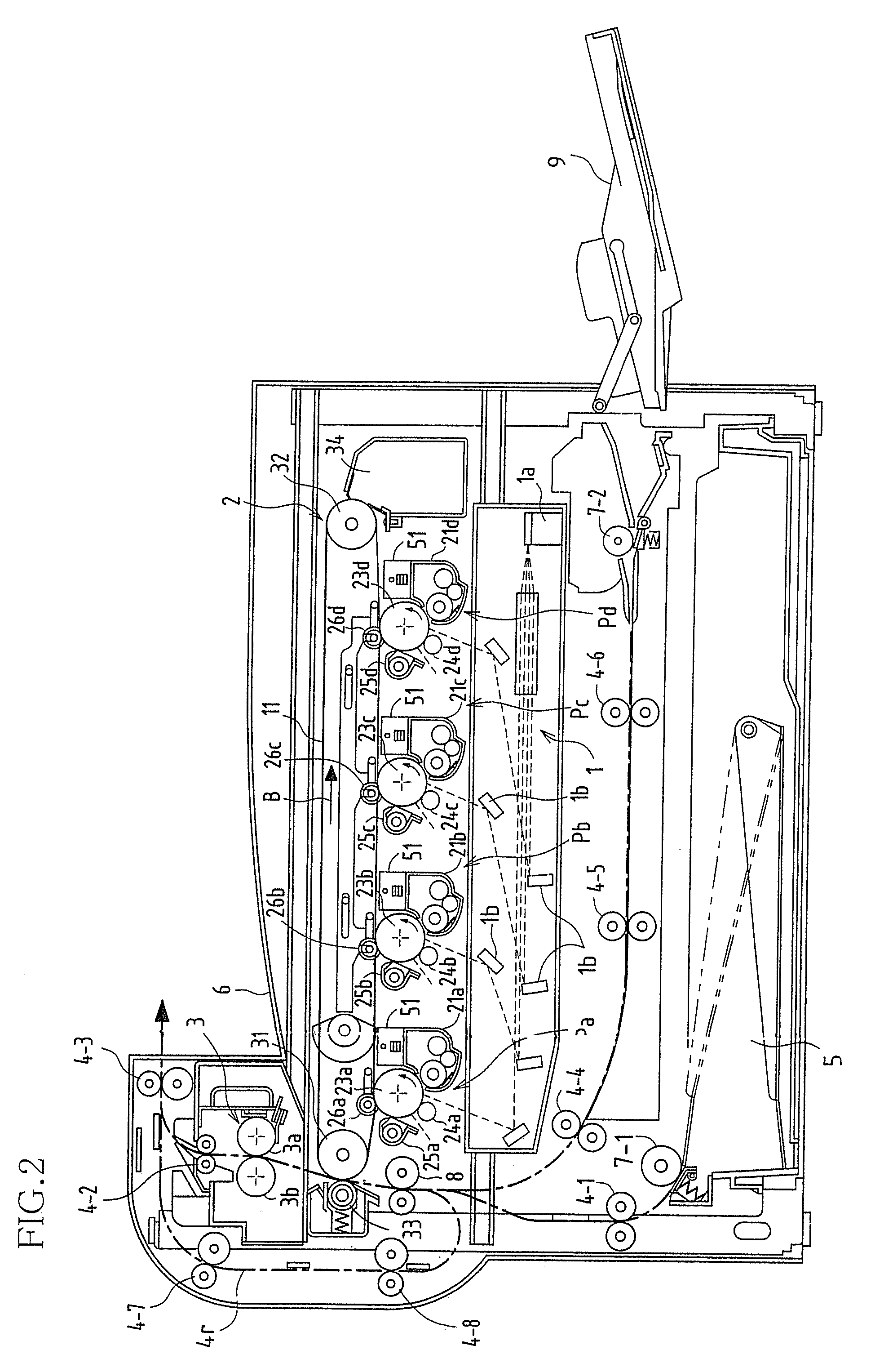
[0055]FIG. 1 is a lateral view showing an Example 1 of an image forming apparatus according to the present invention. The image forming apparatus of the present example is a color laser printer that records a color image on a sheet of recording paper and is provided with an exposure unit 1, image forming stations Pa, Pb, Pc, and Pd, an intermediate transfer belt unit 2, a fixing unit 3, a paper transport system 4, a paper supply tray 5, and a paper discharge tray 6.

[0056]With this image forming apparatus, sheets of recording paper are loaded and stored in the paper supply tray 5, then withdrawn from the paper supply tray 5 sheet by sheet by a pickup roller 7-1 and transported to a register roller 8 by a transport roller 4-1. Alternatively, a sheet of recording paper is loaded in a manual handling tray 9, then withdrawn by a pickup roller 7-2 and transported to the register roller 8 by transport rollers 4-4 to 4-6. The register roller 8 stops the sheet of recording paper, adjusts the...


PUM


Abstract

A pair of indentations is formed with a vertical spacing on a side wall of a toner cartridge, respective translucent windows are arranged on opposing upper and lower surfaces of the indentations protruding into the toner cartridge, and a light-emitting element and a light-receiving element of a remaining toner sensor are inserted to the indentations such that the light-emitting element and the light-receiving element of the remaining toner sensor face each other via the translucent windows of the indentations. When there is sufficient toner remaining in the toner cartridge, there is toner in the space between the transparent plates, and the space between a light-emitting diode and a phototransistor is blocked such that light is not incident on the phototransistor, whereas when there is little toner remaining in the toner cartridge, there is no toner in the space between the transparent plates, and the light is incident on the phototransistor via the space between the light-emitting diode and the photoresistor.

Description

CROSS REFERENCE TO RELATED APPLICATIONS[0001]This application claims priority under 35 U.S.C. § 119(a) on patent application Ser. No. 2003-399728 filed in Japan on Nov. 28, 2003, the entire contents of which are hereby incorporated by reference.BACKGROUND OF THE INVENTION[0002]1. Field of the Invention[0003]The present invention relates to a remaining toner detection apparatus that detects the amount of toner remaining in a toner cartridge of, for example, an electrographic or electrographic image forming apparatus and to an image forming apparatus provided with the same.[0004]2. Description of the Related Art[0005]Commonly known examples of electrographic or electrostatic image forming apparatuses include copying machines, printers, fax machines and the like. In such image forming apparatuses, an electrostatic latent image is formed on a photosensitive base and toner is supplied from a development apparatus to form a toner image on the photosensitive base, after which the electrost...

Claims


Application Information

Patent Timeline
Patent Type & Authority Patents(United States)
IPC IPC(8): G03G15/08G01F23/28G03G15/01G03G21/10
CPCG03G15/0855G03G15/0862G03G15/0856G03G2215/0894
Inventor ISHIGURO, YASUYUKINAKAKUMA, AKIRAKURIMOTO, HIDEAKIMORIMOTO, KIYOFUMI
Owner SHARP KK
Why Eureka
Try Eureka