System and method for operating an engine having an exhaust gas recirculation system

a technology of exhaust gas recirculation and system, which is applied in the direction of exhaust treatment electric control, machines/engines, mechanical equipment, etc., can solve the problems of lowering the temperature within the combustion chamber, lowering the production of no/sub>x, and posing significant challenges to the automotive industry. , to achieve the effect of reducing the flow of exhaust gas and avoiding or lessening the damage of the engin

Active Publication Date: 2007-10-23
FORD GLOBAL TECH LLC
View PDF11 Cites 22 Cited by
  • Summary
  • Abstract
  • Description
  • Claims
  • Application Information

AI Technical Summary

Benefits of technology

[0002]Controlling nitrogen oxide (“NOx”) emissions in internal combustion engines has posed significant challenges to the automotive industry. One method for controlling NOx emissions is generally known as exhaust gas recirculation (EGR). This method utilizes a conduit to recirculate exhaust gases into the engine intake. The recirculated exhaust gases absorb heat in the combustion chamber, thereby lowering the temperatures within the combustion chamber and lowering the production of NOx. A cooler may be provided along the EGR conduit to cool the recirculated exhaust gases and thereby help further lower combustion temperatures.
[0004]A low pressure EGR system may recirculate exhaust gases to the engine intake at a location either upstream or downstream of the intake compressor. In a low pressure EGR system where recirculated exhaust is delivered to the intake upstream of a compressor, particulate matter in the recirculated exhaust can damage the compressor. To help prevent such damage, the low pressure EGR system may draw exhaust from a location downstream of a particulate filter such that particulate matter is removed from the exhaust before it reaches the low pressure EGR intake. However, failure of the particulate filter may occur, in which case particulate matter in the exhaust may damage the intake compressor, EGR cooler, charge air cooler, and / or other engine components.
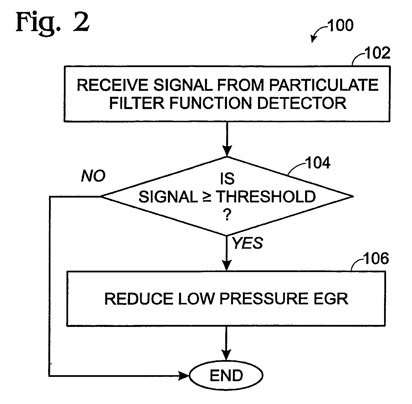
[0005]The inventors herein have realized that particulate damage to an engine may be avoided or lessened in an apparatus having an internal combustion engine, a compressor for compressing engine intake gases, a particulate filter for filtering particulate matter from engine exhaust, an exhaust gas recirculation (EGR) system for recirculating exhaust gases from a location downstream of the particulate filter to a location upstream of the compressor, and a particulate filter function detector configured to detect a failure of particulate filter, by performing a method of operating the engine including receiving a signal from the particulate filter function detector, comparing the signal from the particulate filter function detector to a predetermined signal threshold, determining if the signal received from the particulate filter function detector meets a predetermined condition relative to the predetermined signal threshold; and reducing a flow of exhaust gas through the EGR system if the signal meets the predetermined condition.

Problems solved by technology

Controlling nitrogen oxide (“NOx”) emissions in internal combustion engines has posed significant challenges to the automotive industry.
The recirculated exhaust gases absorb heat in the combustion chamber, thereby lowering the temperatures within the combustion chamber and lowering the production of NOx.
In a low pressure EGR system where recirculated exhaust is delivered to the intake upstream of a compressor, particulate matter in the recirculated exhaust can damage the compressor.
However, failure of the particulate filter may occur, in which case particulate matter in the exhaust may damage the intake compressor, EGR cooler, charge air cooler, and / or other engine components.

Method used


Image

  • System and method for operating an engine having an exhaust gas recirculation system
  • System and method for operating an engine having an exhaust gas recirculation system
  • System and method for operating an engine having an exhaust gas recirculation system

Examples


Embodiment Construction

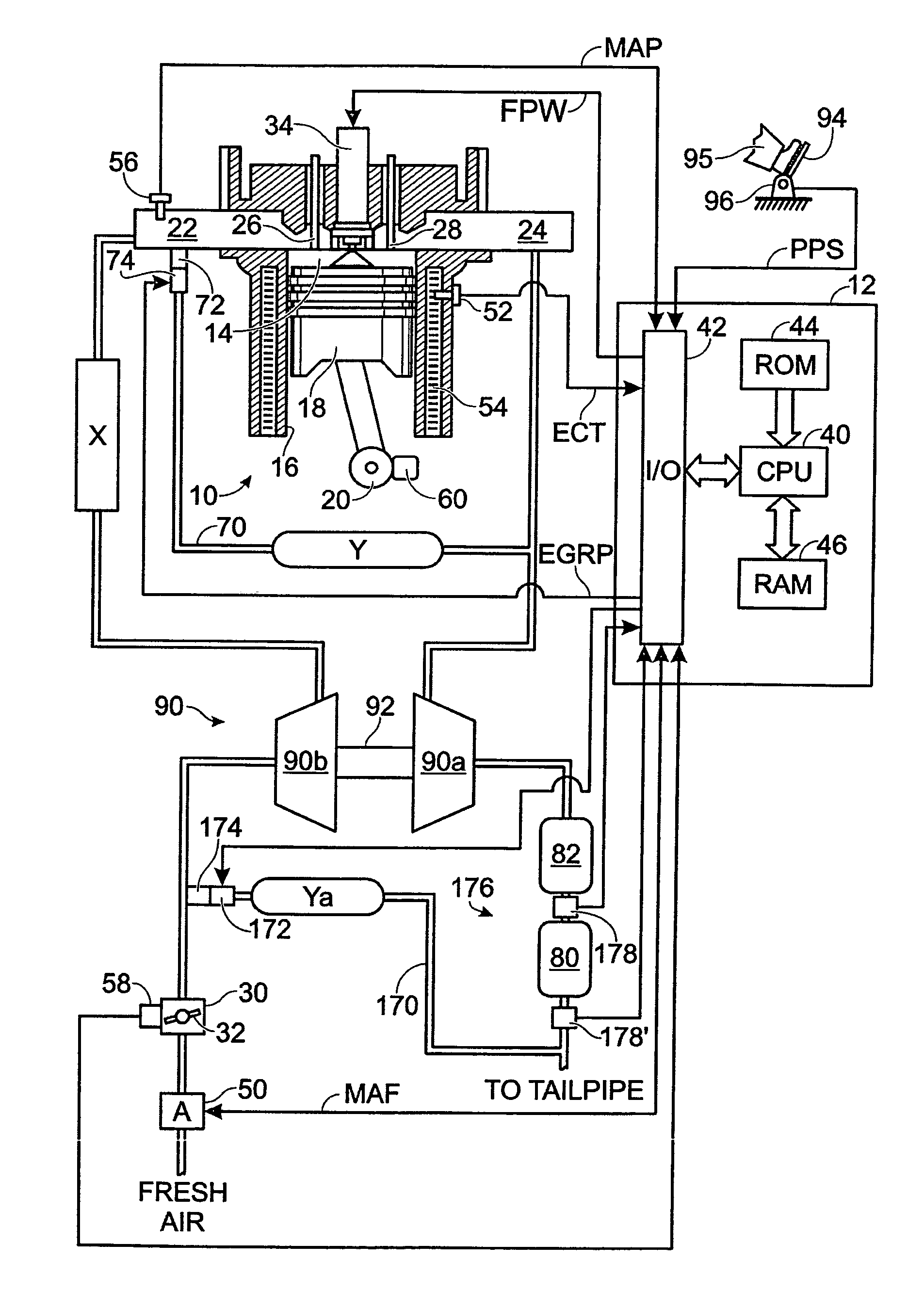
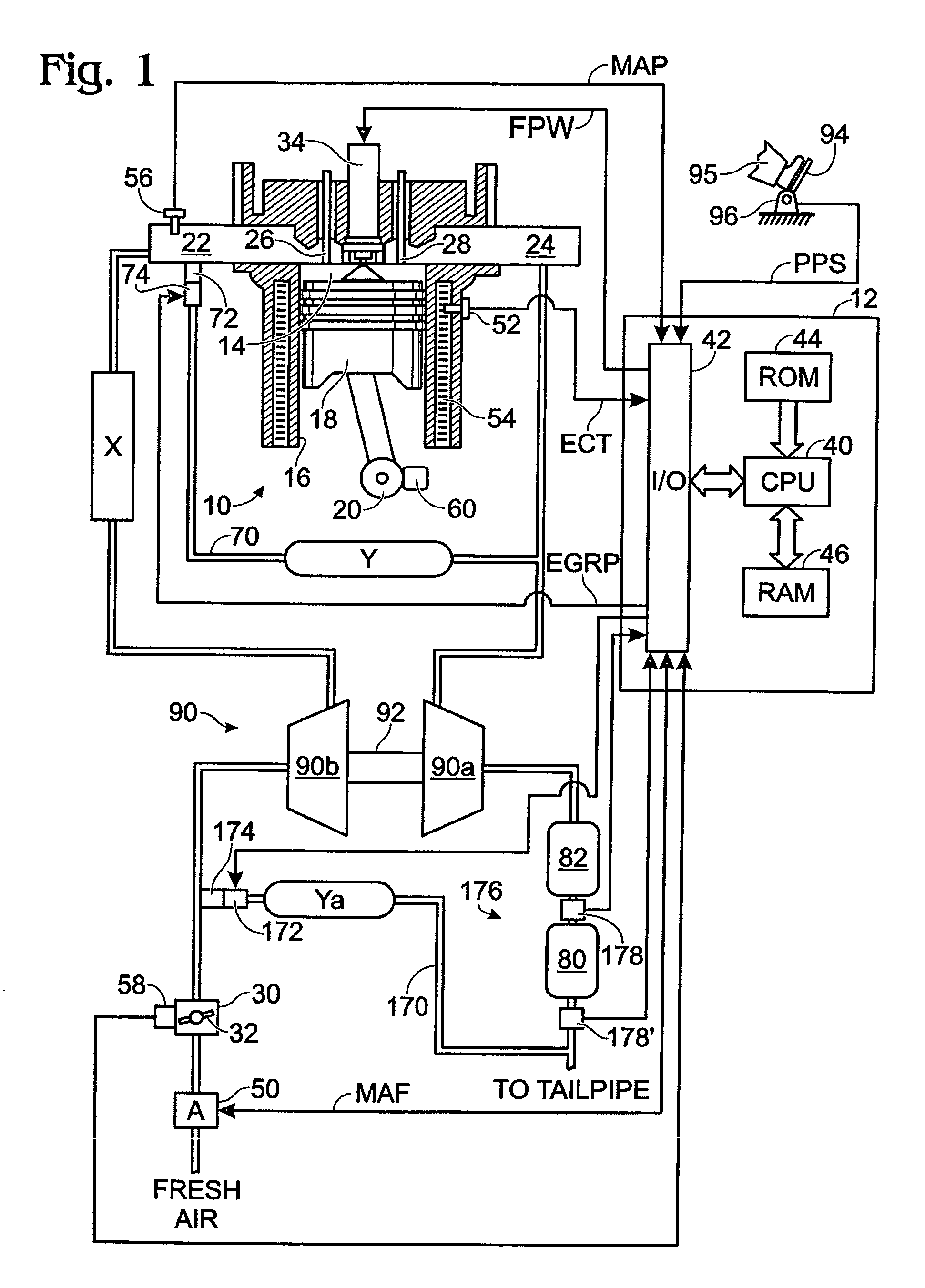
[0008]FIG. 1 shows an example of a diesel engine system generally at 10. Specifically, internal combustion engine 10 comprises a plurality of cylinders, one cylinder of which is shown in FIG. 1. Engine 10 is controlled by electronic engine controller 12. Engine 10 includes combustion chamber 14 and cylinder walls 16 with piston 18 positioned therein and connected to crankshaft 20. Combustion chamber 14 communicates with an intake manifold 22 and an exhaust manifold 24 via respective intake valve 26 and exhaust valve 28.

[0009]Intake manifold 22 communicates with throttle body 30 via throttle plate 32. In one embodiment, an electronically controlled throttle can be used. In one embodiment, the throttle is electronically controlled to periodically, or continuously, maintain a specified vacuum level in intake manifold 22. While throttle body 30 is depicted as being upstream of a compressor device 90b, it will be appreciated that the throttle body may be placed upstream or downstream of ...


PUM


Abstract

In an apparatus having an internal combustion engine, a compressor for compressing engine intake gases, a particulate filter for filtering particulate matter from engine exhaust, an exhaust gas recirculation (EGR) system for recirculating exhaust gases from a location downstream of the particulate filter to a location upstream of the compressor, and a particulate filter function detector configured to detect a failure of the particulate filter, a method of operating the engine, including receiving a signal from the particulate filter function detector, comparing the signal from the particulate filter function detector to a predetermined signal threshold, determining if the signal received from the particulate filter function detector meets a predetermined condition relative to the predetermined signal threshold; and reducing a flow of exhaust gas through the EGR system if the signal meets the predetermined condition.

Description

TECHNICAL FIELD[0001]The present application relates to the field of automotive emission control systems and methods.BACKGROUND AND SUMMARY[0002]Controlling nitrogen oxide (“NOx”) emissions in internal combustion engines has posed significant challenges to the automotive industry. One method for controlling NOx emissions is generally known as exhaust gas recirculation (EGR). This method utilizes a conduit to recirculate exhaust gases into the engine intake. The recirculated exhaust gases absorb heat in the combustion chamber, thereby lowering the temperatures within the combustion chamber and lowering the production of NOx. A cooler may be provided along the EGR conduit to cool the recirculated exhaust gases and thereby help further lower combustion temperatures.[0003]In a turbocharged engine, two types of EGR systems may be employed. The first may be referred to as a high pressure EGR system, and recirculates exhaust from a location upstream of the exhaust turbine. The second may b...

Claims


Application Information

Patent Timeline
Patent Type & Authority Patents(United States)
IPC IPC(8): F01N3/00
CPCF01N3/023F01N11/00F01N9/00Y02T10/47Y02T10/40
Inventor KURTZ, ERIC
Owner FORD GLOBAL TECH LLC
Why Eureka
Try Eureka