Vibration damping mount and metal heat shield

a technology of vibration damping and metal heat shield, which is applied in the direction of shock absorbers, ring springs, machines/engines, etc., can solve the problems of difficult to improve the sound insulation performance of conventional techniques, the cracks in metal heat shields can be prevented, and the quality of metal heat shields can be improved remarkably. , the effect of improving the vibration characteristic of metal heat shield

Inactive Publication Date: 2007-10-23
SANWA PACKING IND
View PDF8 Cites 29 Cited by
  • Summary
  • Abstract
  • Description
  • Claims
  • Application Information

AI Technical Summary

Benefits of technology

[0023]The present invention has been devised in order to solve the problems inherent in the heat shield and the vibration damping mount of the conventional techniques. It is an object of the present invention to provide a vibration damping mount with which the breakage due to wearing and the occurrence of electrolysis are prevented and the vibration damping action is improved remarkably and to provide a metal heat shield with which the sound insulation performance is improved remarkably.

Problems solved by technology

Consequently, a problem occurs in that a crack tends to be caused in a portion where the heat shield is attached to the bolt or the like, and durability is deteriorated.
Therefore, there is a problem in that it is difficult to improve the sound insulation performance with such a conventional technique.
Further, the conventional technique has problems as described below.
Consequently, problems such as an increase of noise and formation of a crack in the heat shield 3 occur, and a problem arises in a quality of the heat shield 3.
Consequently, temperature of the heat shield 3 rises, and the radiant heat increases to easily damage, for example, auxiliary devices, ducts, and harnesses around the engine 1 in a hood due to heat.
Therefore, a problem arises in a quality as a heat shield.
Consequently, it is assumed that a problem may occur in that the compression and restoration characteristics of the damping sheets 16 and 17 are degraded and the action of controlling a vibration is degraded.
In addition, since the damping sheets 16 and 17 are formed of the inorganic fiber, the expand metal, or the like, it is assumed that a problem may occur in that the fiber decomposes and flies as time elapses.
In these regards, it is considered that the technique shown in FIG. 41 has a problem in that a quality with respect to a vibration damping action is low.
However, such conventional techniques have problems to be explained below.
In addition, it is assumed that contact portions of the grommet 20 and the attachment boss 10 wear with time due to this contact to result in breakage.
Consequently, a problem arises in a quality of the vibration damping mount 11b.
As a result, again, a problem arises in the quality of the vibration damping mount 11b.

Method used


Image

  • Vibration damping mount and metal heat shield
  • Vibration damping mount and metal heat shield
  • Vibration damping mount and metal heat shield

Examples


first embodiment

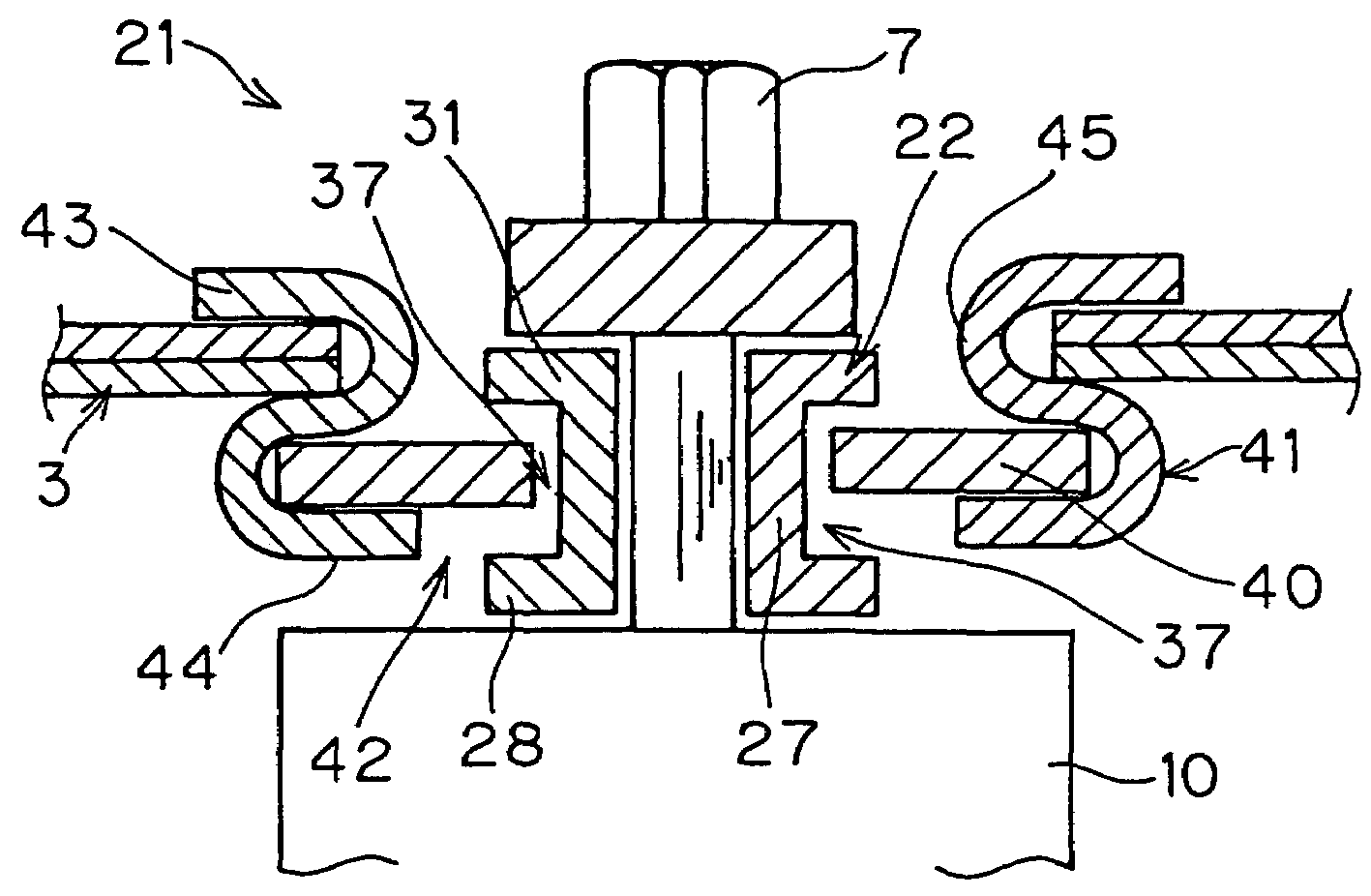
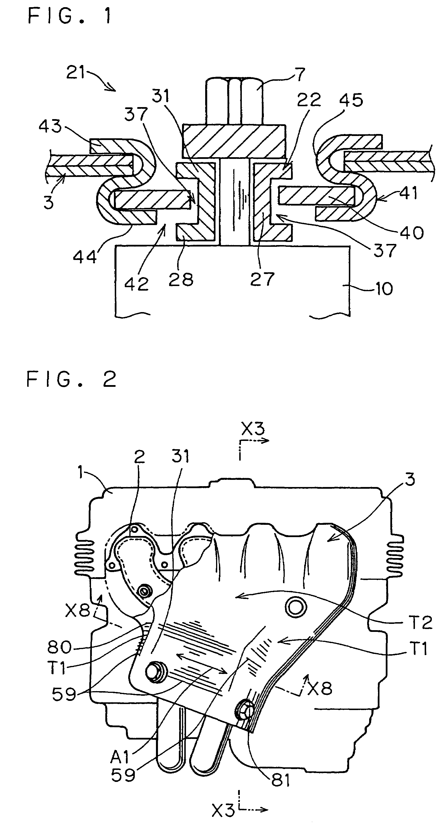
[0103]FIGS. 1 to 9 show a first embodiment of the present invention.

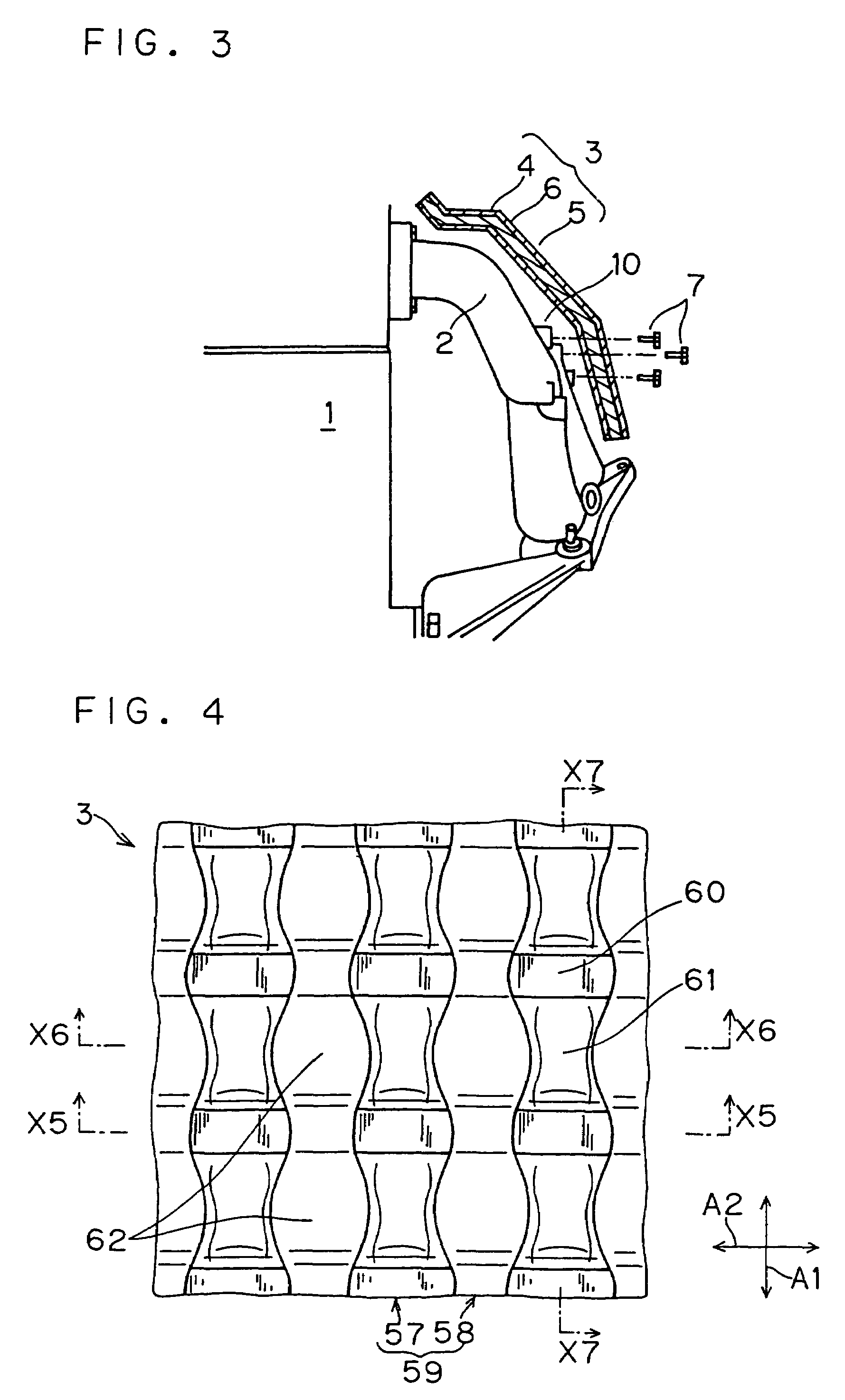
[0104]FIG. 1 is a sectional view schematically showing a state in which a vibration damping mount 21 of this embodiment is used. FIG. 2 is a front view of an engine 1 showing a structure forming a basis of the present invention. FIG. 3 is a sectional view of the engine 1 viewed from a section line X3-X3 in FIG. 2. FIG. 4 is an enlarged front view of a metal exhaust manifold heat shield (hereinafter referred to as heat shield) 1 of an embodiment of the present invention. FIG. 5 is a sectional view of the heat shield viewed from a section line X5-X5 in FIG. 4. FIG. 6 is a sectional view of the heat shield viewed from a section line X6-X6 in FIG. 4. FIG. 7 is a sectional view of the heat shield viewed from a section line X7-X7 in FIG. 4. FIG. 8 is a simplified sectional view of the engine 1 viewed from a section line X8-X8 in FIG. 2. FIG. 9 is a view illustrating characteristics of this embodiment.

[0105]This embodiment...

second embodiment

[0136]FIG. 10 is a sectional view schematically showing a vibration damping mount 21a according to a second embodiment of the present invention. FIG. 11 is a sectional view showing a principle of this embodiment. FIG. 12 is an enlarged sectional view showing the principle of this embodiment. FIG. 13 is a graph showing an effect of this embodiment.

[0137]The vibration damping mount 21a according to the second embodiment of the present invention will be explained with reference to FIGS. 10 to 13.

[0138]This embodiment is similar to the above-mentioned embodiment. Components corresponding to those in the above-mentioned embodiment are denoted by the identical reference numerals and signs. In this embodiment, when the heat shield 3 is attached to the exhaust manifold 2, the vibration damping mount 21a shown in FIG. 10 is used. The vibration damping mount 21a includes: a collar member 22; spring washers 23 and 24, which are damping members with thickness t1, mounted on the collar member 22...

third embodiment

[0150]FIG. 14 is a sectional view of a vibration damping mount 21b of a third embodiment of the present invention. FIG. 15 is a sectional view of a comparative example of this embodiment. FIG. 16 is a sectional view showing characteristics of the vibration damping mount 21b. FIG. 17 is a plan view of spring washers 23 and 24 of the vibration damping mount 21b. FIG. 18 is a perspective view of the spring washers 23 and 24. FIG. 19 is a perspective view of a comparative example for the vibration damping mount 21b. FIG. 20 is a sectional view of the comparative example. FIG. 21 is a sectional view showing an operational example of the vibration damping mount 21b. FIG. 22 is a sectional view showing another operational example of the vibration damping mount 21b. FIG. 23 is a sectional view showing yet another operational example of the vibration damping mount 21b. FIG. 24 is a graph illustrating an action of this embodiment.

[0151]The vibration damping mount 21b of this embodiment will b...


PUM


Abstract

A vibration damping mount includes: a substantially annular damping member having an insertion hole, through which the bolt to be attached to an attachment boss is inserted, and externally surrounds the bolt; a grommet that includes a first retaining section for retaining a heat shield, a second retaining section for retaining the damping member, and a coupling section for coupling the first retaining section and the second retaining section, the second retaining section, the coupling section, and the first retaining section being provided in this order from the attachment boss side; and a collar member that includes a pair of flange sections, which nip the damping member from both sides in an axial direction with gaps formed on both the sides, and a coupling section, which couples the pair of flange sections each other and has a gap in a radial direction between the coupling section and the damping member.

Description

BACKGROUND OF THE INVENTION[0001]The present invention relates to a vibration damping mount that is used for mounting, for example, a heat shield or a housing on a member generating a vibration or heat, and relates to a metal heat shield that can be attached to, for example, an exhaust manifold of an internal combustion engine using such a vibration damping mount.[0002]A heat shield, which is an example of such a metal exhaust manifold heat shield or housing, is used in an automobile. Such a heat shield, for example, a part near an exhaust manifold mounted on an engine of an automobile so as to control heat and sound from the exhaust manifold not to propagate to the periphery of the engine. Such a heat shield is attached to the exhaust manifold by a screw member such as a bolt.[0003]FIG. 2 is a front view of an engine 1 of a vehicle such as an automobile showing a basic structure of this conventional technique. FIG. 40 is a sectional view of the conventional technique. The conventio...

Claims


Application Information

Patent Timeline
Patent Type & Authority Patents(United States)
IPC IPC(8): F16F15/00F01N13/08B41J19/04F01N13/10F01N13/14F02B77/11F02B77/13F16F15/06
CPCF01N13/14F16F15/06F02B77/13F02B77/11F01N2260/20F01N13/08B41J19/04
Inventor MISHIMA, KAZUAKI
Owner SANWA PACKING IND
Why Eureka
Try Eureka