Sanding attachment for a reciprocating power tool

Inactive Publication Date: 2007-10-23
JIOIA LES
View PDF8 Cites 16 Cited by
  • Summary
  • Abstract
  • Description
  • Claims
  • Application Information

AI Technical Summary

Benefits of technology

[0014]It is a further object of the invention to provide a sanding attachment which is rugged and will not become damaged or deformed even after repeated use. Accordingly, the sanding attachment is fashioned from a strip of durable, resilient metal, and will not become damaged or deformed even after repeated use.
[0015]It is yet another object of the invention to provide a sanding attachment which is not unduly expensive. Accordingly, the sanding attachment is constructed from readily available materials, and its cost is not prohibitive.
[0016]It is a still further object of the invention to provide a sanding attachment which allows a variety of sanding operations to be performed. Accordingly, the sanding pad can take the form of a variety of sanding accessories having varied sanding surfaces, that are selectively attached to the sanding end.
[0017]The invention is a sanding attachment, f

Problems solved by technology

Many existing reciprocating tools are not furnished with sanding attachments for abrading a rough surface of an existing object,

Method used


Image

  • Sanding attachment for a reciprocating power tool
  • Sanding attachment for a reciprocating power tool
  • Sanding attachment for a reciprocating power tool

Examples


Embodiment Construction

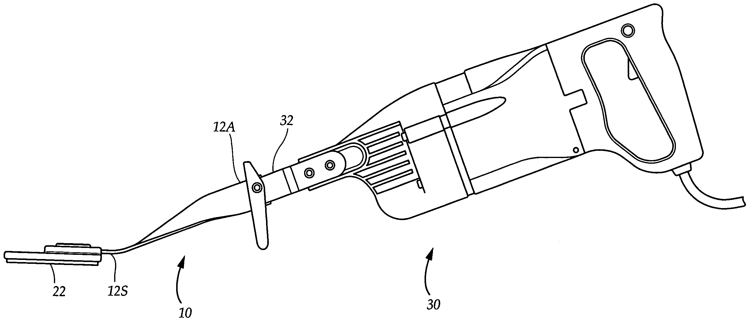
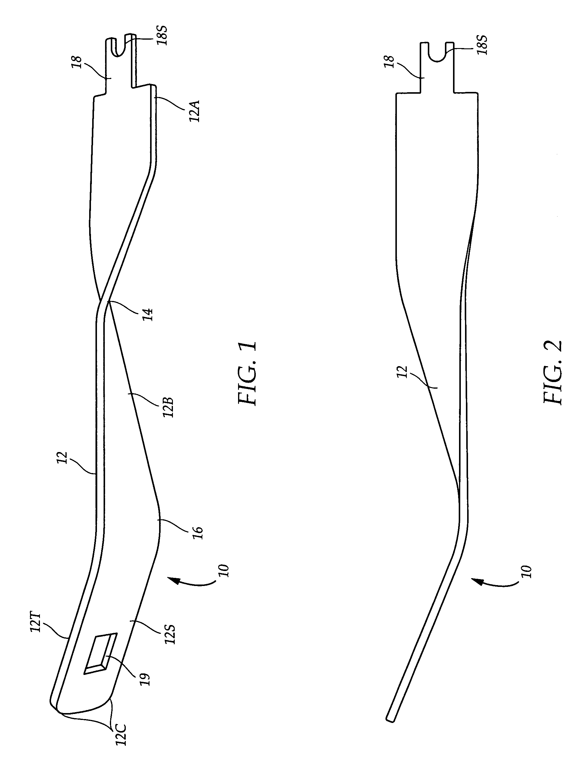
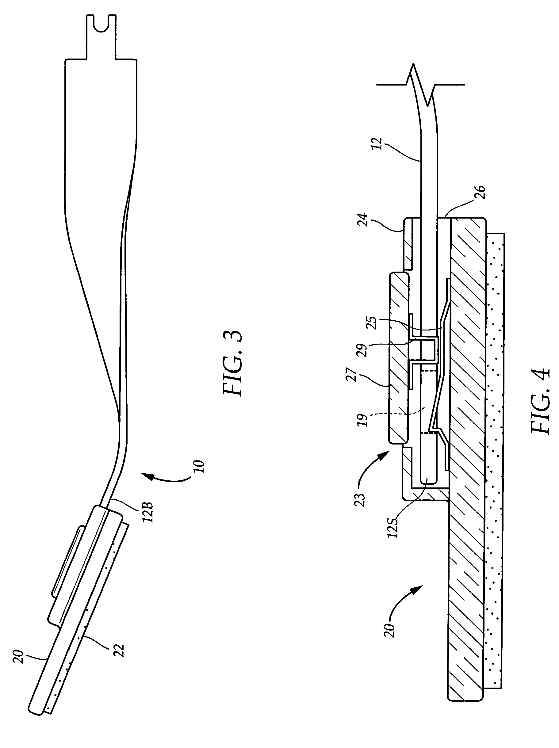
[0027]FIG. 1 illustrates a main part 12 of a sanding attachment 10, for use in conjunction with an existing reciprocating power tool, for sanding rough surfaces of an existing object. The main part 12 comprises an elongated, substantially rectangular strip of metal of substantially uniform thickness, having a top surface 12T, a bottom surface 12B, an attachment end 12A for selective attachment to the power tool, and a sanding end 12S which is directed at a surface to be smoothed or abraded. In this regard, referring to FIG. 3, attached to the bottom surface 12B of the sanding end 12S is a sanding pad 20 having a sanding surface 22. The sanding surface 22 has a plurality of small, raised protuberances for rapidly and efficiently abrading a rough surface when the sanding attachment 10 is being deployed. To accomplish the attachment of the sanding pad 20, the sanding end 12S has a substantially square fastening opening 19 extending fully between the top surface 12T and bottom surface 1...


PUM

PropertyMeasurementUnit
Angleaaaaaaaaaa
Resilienceaaaaaaaaaa

Abstract

A sanding attachment, for use in conjunction with an existing reciprocating power tool, for sanding a rough surface of an existing object. The sanding attachment comprises a main part being an elongated strip of metal having an attachment end for selective attachment to the power tool, and a sanding end. Attached to the sanding end is a sanding pad having a sanding surface for efficiently sanding an object. The sanding attachment has a twist which results in the attachment end and the sanding end being substantially mutually perpendicular to one another. After the sanding attachment has been selectively attached to the power tool, and the power tool is held within the hands of the user is the usual fashion, the sanding attachment is suitably positioned for efficiently sanding a substantially horizontal surface.

Description

CROSS REFERENCES AND RELATED SUBJECT MATTER[0001]This application is a continuation-in-part of patent application Ser. No. 10 / 771,479, filed in the United States Patent Office on Feb. 4, 2004 now abandoned.BACKGROUND OF THE INVENTION[0002]1. Field of the Invention[0003]The invention generally relates to an accessory for a power tool, and in particular relates to a sanding attachment for a reciprocating power tool.[0004]2. Description of the Related Art[0005]Reciprocating power tools are utilized for performing tasks wherein rapid back-and-forth motion of an attachment, such as a saw blade, is required. By way of example, a Sawzall reciprocating saw is utilized for rapidly and efficiently cutting wood and other construction materials. Many existing reciprocating tools are not furnished with sanding attachments for abrading a rough surface of an existing object, or if they are so furnished, the attachment provided is not suitably configured to rapidly and efficiently abrade rough surf...

Claims


Application Information

Patent Timeline
IPC IPC(8): B24B1/00B24B27/08
CPCB24B23/04B24B23/005
Inventor JIOIA, LES
Owner JIOIA LES
Why Eureka
Try Eureka