
Portable rotary brush cleaning device

Inactive Publication Date: 2006-12-05
KATO BARBARA
View PDF6 Cites 9 Cited by
  • Summary
  • Abstract
  • Description
  • Claims
  • Application Information

AI Technical Summary

Benefits of technology

[0007]It is an object of the invention to provide a cleaning device which has a brush which is capable of rotating intermittently, according to the needs of the user. Accordingly, this device has a brush which is attachable to a brush motor which is located in the brush handle, and thereby provides the user with a choice of brush speeds to be used for different surfaces.
[0008]It is a further object of the invention to provide a cleaning device which may be easily moved between various locations within the home. Accordingly, the device is equipped with two side wheels on its bottom surface, so that it may be rolled between locations without the necessity of lifting the device.
[0009]It is another object of the invention to provide a cleaning device which is relatively inexpensive and whose cost is not prohibitive. Accordingly, the functional components of this device, including a motor which rotates the brush and pumps which furnish the brush with water and cleaning solution, are not complex and do not make the cost of this device unduly expensive.
[0010]It is yet another object of the invention to provide a cleaning device which is relatively lightweight and which can therefore be easily carried between different locations. Accordingly, this device is equipped with a handle on its upper surface, by which the device may be easily carried. Furthermore, this device is comprised of components which are not unduly heavy, and the device may be easily carried by most homeowners. Additionally, the brush handle and the tanks which hold the cleaning solution may be removed from the body of the machine before attempting to lift the device. Moreover, the water tank may be drained. These features therefore contribute to enhanced portability of the device.

Problems solved by technology

Some of these surfaces are relatively inaccessible and may only be reached by bending and consequently, a homeowner may hurt his / her back while attempting to reach these surfaces.

Method used


Image

  • Portable rotary brush cleaning device
  • Portable rotary brush cleaning device
  • Portable rotary brush cleaning device

Examples


Embodiment Construction

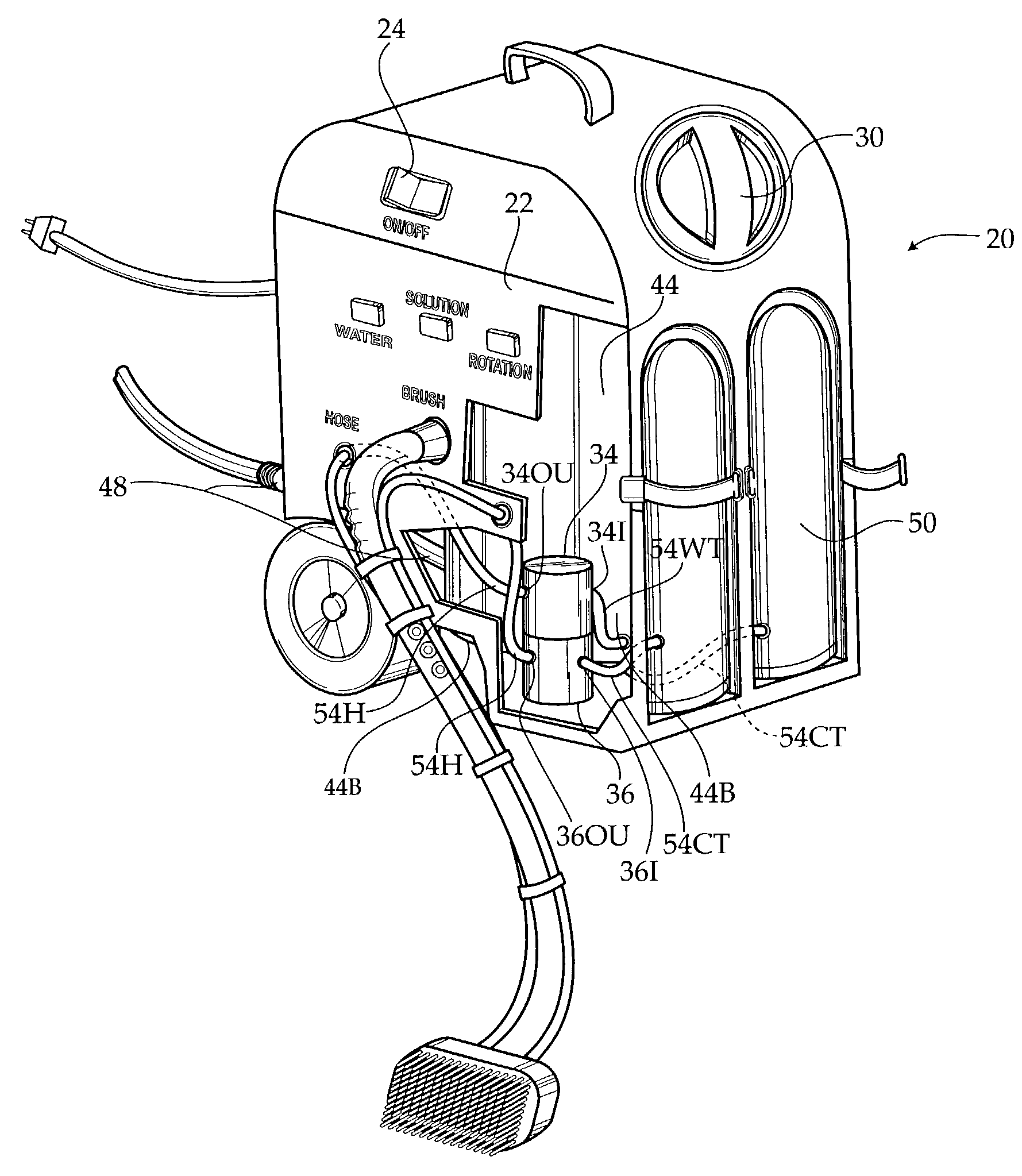
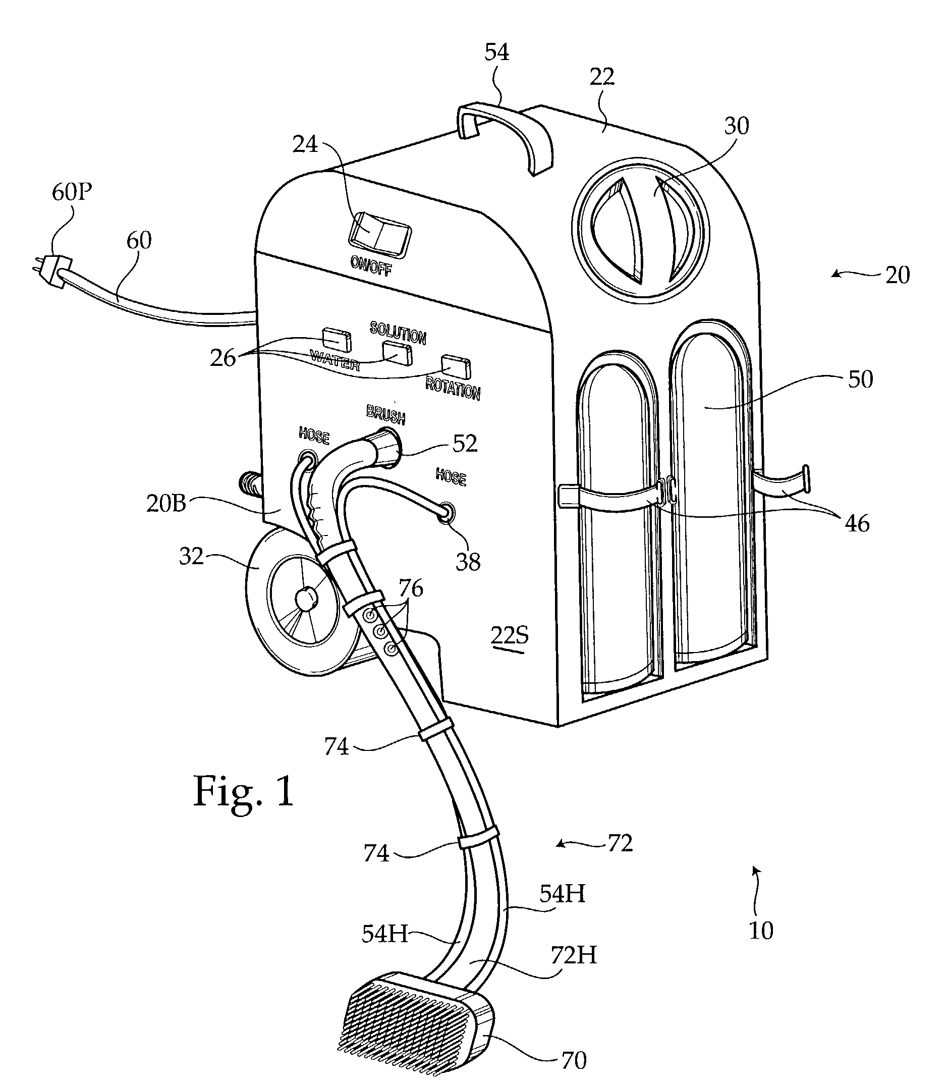
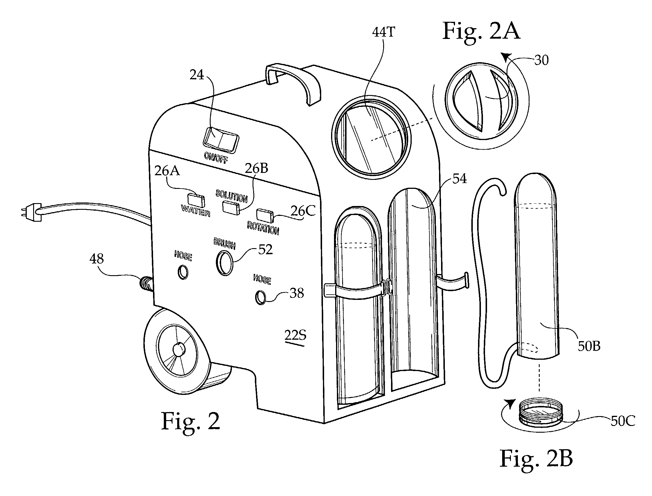
[0023]FIG. 1 illustrates the portable rotary brush cleaning device 10, which is comprised of a machine body 20 having a bottom portion 20B, a machine housing 22, and two side wheels 32 located near the bottom portion 20B of the machine body 20. The cleaning device 10 further has a brush handle 72, a brush 70, and brush handle hoses 54H which extend along the brush handle 72 from the machine body 20 to the brush 70. Integral components of the machine body 20 are enclosed by the machine housing 22. The device has an electrical cord 60 having a plug 60P, and a water tank drain 48 which enter the machine body 20 through openings on the machine housing 22. A pair of cleaning solution tanks 50 are mounted external to the housing 22.

[0024]Turning momentarily to FIG. 6, which is a perspective view of the device 10 with a portion of the machine housing 22 cut away in order that the components of the machine body 20 may be more easily seen, the machine body 20 is seen to comprise a water tank...


PUM


Abstract

A portable rotary brush cleaning device for cleaning the inside of a bathtub or other household surfaces, comprising a machine body, a brush handle having two ends, and a motor-driven brush. The brush handle is attached to the machine body at one of its ends and to the brush at its other end. The machine body houses a water tank, a cleaning solution tank, a water pump, and a cleaning solution pump. The pumps supply water and cleaning solution to the brush via hoses that run along the length of the brush handle. A user first wets the brush by activating buttons which control the pumps. The user then activates the motor which causes the brush to rotate upon the brush handle. The user alternates between wetting the brush and rotating the brush on the surface to be cleaned, until the surface has been sufficiently cleaned.

Description

BACKGROUND OF THE INVENTION[0001]1. Field of the Invention[0002]The invention relates to a portable rotary brush cleaning device which may be used to clean the inside of a bathtub, or floors, or other household surfaces. The device has a machine body, a brush handle which is attachable to the machine body, and a variety of brushes which are selectively attachable to the brush handle. The machine body houses tanks which separately contain cleaning solution and water, pumps for pumping these liquids to the brushes, and hoses which connect the tanks to the pumps. These hoses ultimately lead to the brush and wet the brush bristles, thereby increasing the efficiency of cleaning. A motor in the brush handle selectively rotates the brush.[0003]2. Description of the Related Art[0004]A variety of surfaces located in the home require periodic cleaning by a homeowner. Some of these surfaces are relatively inaccessible and may only be reached by bending and consequently, a homeowner may hurt hi...

Claims


Application Information

Patent Timeline
IPC IPC(8): A46B13/00A46B13/04A47L11/00
CPCA46B13/04A47L13/26
Inventor KATO, BARBARA
Owner KATO BARBARA
Learn More