Die for a tool set for mechanical joining

a technology of mechanical joining and tool sets, which is applied in the direction of shaping tools, forging hammers, metal rolling, etc., can solve the problems of increasing the risk of fracture of the die base body, short service life of such a die, and skewed and jamming, so as to improve the guidance properties of the displaceable die segmen

Inactive Publication Date: 2007-10-30
JAGAO
View PDF15 Cites 17 Cited by
  • Summary
  • Abstract
  • Description
  • Claims
  • Application Information

AI Technical Summary

Benefits of technology

[0008]A die for a tool set for mechanical joining is provided which provides a respective guideway in the die sleeve to each of the die segments. During their displacement directed radially relative to an anvil, the die segments are supported on a supporting surface of a die base body, and are additionally guided directly by the die segment sections which engage in the die sleeve in a slidable manner. Such a die is of compact construction with regard to die height and die diameter and has improved guidance properties for the displaceable die segments.
[0009]To achieve this end, the die sleeve has apertures which preferably pass completely through the die sleeve wall and in which the die segments engage by means of a respective extension. The radial displacement path of the die segments lies within the segment guides and therefore leads to no increased extension of the tool in the radial direction. In addition, it is advantageous that dirt can be discharged from the die, as a result of which the service life of the latter can be further improved.
[0010]The segment guides in the die sleeve form closed guides which allow sliding of the die segments radially relative to the anvil and at the same time limit axial displacement of the said die segments. The undercuts required in the prior art on the die segments for securing the same against axial displacement from the supporting surface can be dispensed with. The die segments and thus the entire die can consequently have a smaller overall axial height. In this case, the reduced ratio, compared with the prior art, of axial extent to radial extent of the die segments leads at the same time to greater stability against tilting during the radial displacement.
[0012]The spring preloading is preferably exerted by an elastic ring, which in particular may be a metal spring. For reliable mounting of the elastic ring, the die segments can each have a groove running in the circumferential direction.

Problems solved by technology

A disadvantage in this case is that the die segments, on account of their unfavourable ratio of overall height to radial extent, are more likely to tilt than to slide radially and in the process can become skewed and jammed as a result.
This results in an increased risk of fracture of the die base body.
The service life of such a die is therefore short.
Furthermore, the annular element on the anvil body requires an increased overall height, as a result of which the accessibility of the joints in shaft-like components is greatly restricted.
A disadvantage in this case is again that the die segments can become skewed relative to the projecting guides and can become jammed as a result.
A disadvantage here is that the die segments can become skewed relative to the longitudinal holes, since the displacement is effected against a stop, the die segments being guided solely by supported pins.

Method used


Image

  • Die for a tool set for mechanical joining
  • Die for a tool set for mechanical joining
  • Die for a tool set for mechanical joining

Examples


Embodiment Construction

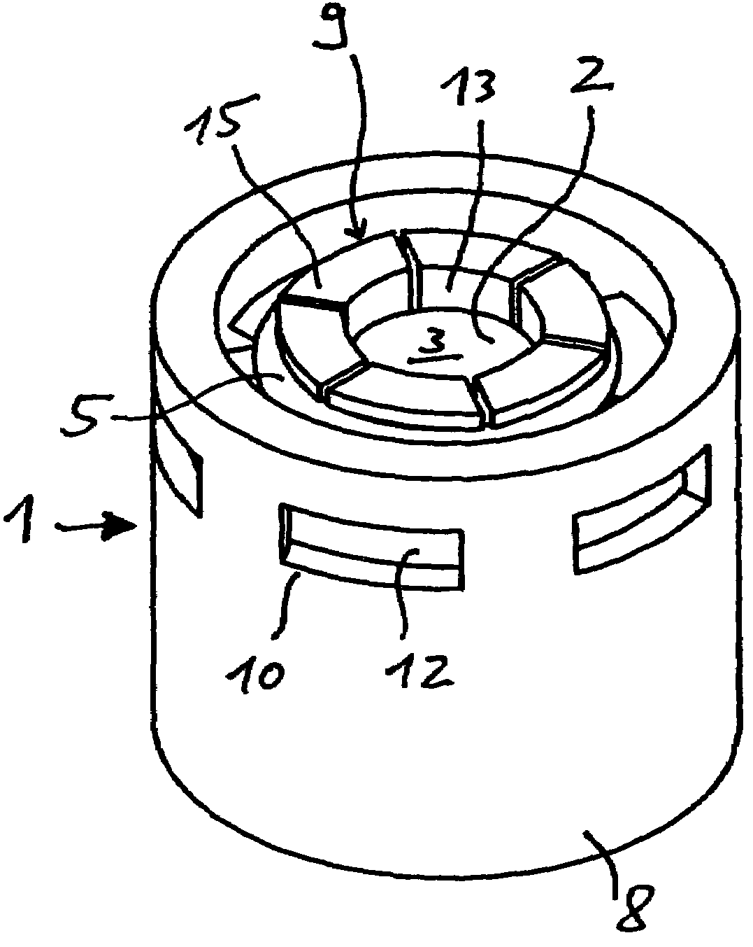
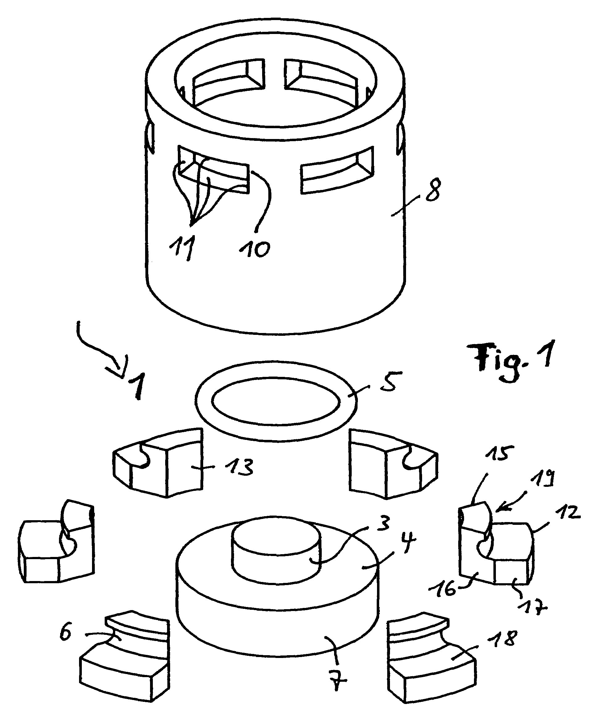
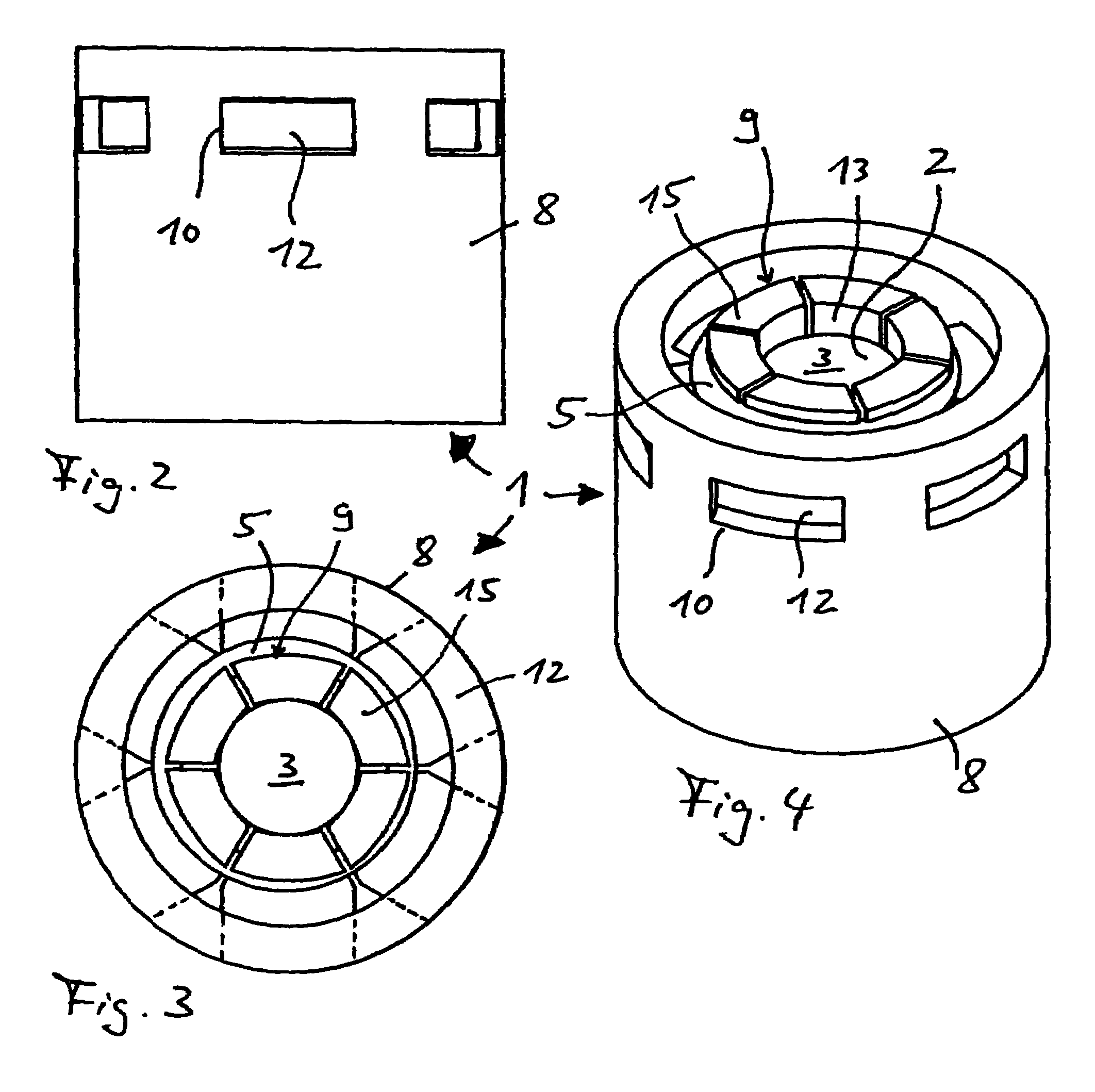
[0021]FIGS. 1 to 5 show a first exemplary embodiment of a die 1 for a tool set for the mechanical joining of sheets resting one on top of the other in a planar manner by forming with at least one punch (not shown) and a die 1. The die 1 defines a cavity 2 (cf. FIG. 4) into which joining is effected. To this end, the die 1 comprises an anvil 3 with a head-side anvil face, against which the punch can be moved. Provided on the anvil 3 are individual die segments 9 which define the cavity 2 in the circumferential direction and which, when the punch is being fed in the direction of the anvil 3, execute a yielding movement transversely to an axial extent of the anvil 3 and thus transversely to the punch feed direction. To this end, the die 1 preferably comprises an anvil 3 which is designed as a straight circular cylinder and is formed on a die base body 7.

[0022]Provided on the die base body 7 concentrically to the anvil 3 is a flat supporting surface 4, relative to which the anvil 3 proj...


PUM

PropertyMeasurementUnit
axial displacementaaaaaaaaaa
shapeaaaaaaaaaa
thicknessaaaaaaaaaa

Abstract

A die for a tool set includes at least one punch and a die which defines a cavity for effecting joining. The die comprises an anvil opposite the punch. Die segments adjoin the said anvil and define the cavity in the circumferential direction. When the punch is being fed in the direction of the anvil, the segments execute a yielding movement transversely to the punch feed direction.

Description

BACKGROUND OF THE INVENTION[0001]The invention relates to a die for a tool set for mechanical joining.[0002]EP 0 779 843 B1 discloses a tool set for producing joints on plate-shaped parts, this tool set having a first top tool part with a punch and a second bottom tool part with a round die. The die has an anvil with an anvil body, on which an annular element with a head-side sliding surface and a base-side connection surface are provided. Individual die segments which surround the anvil and are in the shape of ring sections have recesses for concentric flanging of the said die segments to the annular element, this flanging allowing a longitudinally directed movement of the die segments, each die segment being supported in a displaceable manner on the head-side sliding surface under spring preloading, for which purpose an elastic device brings the die segments to bear against the side surface of the anvil.[0003]A disadvantage in this case is that the die segments, on account of thei...

Claims


Application Information

Patent Timeline
Patent Type & Authority Patents(United States)
IPC IPC(8): B21B25/00B21D26/00B21D41/00B23P11/00B21D37/02B21D39/03
CPCB21D39/031Y10T29/49835
Inventor KUHNE, TIMM
Owner JAGAO
Why Eureka
Try Eureka