Vehicle fuel supply construction

a technology of vapor return circuit and fuel supply construction, which is applied in the direction of liquid fuel feeders, machines/engines, cycle equipment, etc., can solve the problems of complex assembly and construction, and achieve the effects of suppressing reducing the thermal effect of the exhaust pipe, and reducing the generation of vapor

Inactive Publication Date: 2007-10-30
HONDA MOTOR CO LTD
View PDF13 Cites 6 Cited by
  • Summary
  • Abstract
  • Description
  • Claims
  • Application Information

AI Technical Summary

Benefits of technology

[0028]According to the first aspect of the present invention, since the fuel pump that is disposed separately from the fuel tank is integrated with the auxiliary fuel tank, there is no need to return surplus fuel to the fuel tank by a fuel return tank, and therefore, such a fuel return pipe can be omitted. In addition, since only vapor is returned to the fuel tank by the exclusive vapor return unit, vapor can be returned to above the fuel level resulting when the fuel tank is topped up, thereby making it possible to prevent the mixture of vapor into fuel in the fuel tank.
[0029]According to the second embodiment, since the fuel pump is disposed on the opposite side of the vehicle body to the side thereof where the exhaust pipe is disposed, the fuel pump can be disposed away from the exhaust pipe, so that the thermal effect of the exhaust pipe is reduced to thereby suppress the generation of vapor.
[0030]According to the third aspect of the present invention, since the fuel pump is disposed back of the engine cooling fan, the fuel pump can be cooled by the engine cooling fan, so that the fuel pump is subjected to thermal effect of the engine with difficulty. Due to this, the generation of vapor can further be suppressed.
[0031]According to the fourth aspect of the present invention, since the fuel pump is disposed below the fuel tank, pipings for fuel supply and the vapor return unit can be made short and easy. Moreover, since vapor is allowed to rise smoothly from the fuel pump below towards the fuel tank disposed thereabove, the return of vapor can be ensured.
[0032]According to the fifth aspect of the present invention, since part of the piping of the vapor return unit is laid along the external surface of the fuel tank so as to communicate and connect with the interior of the fuel tank at the position above the fuel level resulting when the fuel tank is filled up, there is no need to pass the piping through the bottom surface of the fuel tank, facilitating the sealing of the connecting portion is facilitated, and the assembling and building can be facilitated.

Problems solved by technology

Moreover, when attempting to make an end portion of the fuel return pipe pass into the interior of the fuel tank from a bottom portion thereof, assembling and building become complicated.

Method used


Image

  • Vehicle fuel supply construction
  • Vehicle fuel supply construction
  • Vehicle fuel supply construction

Examples


Embodiment Construction

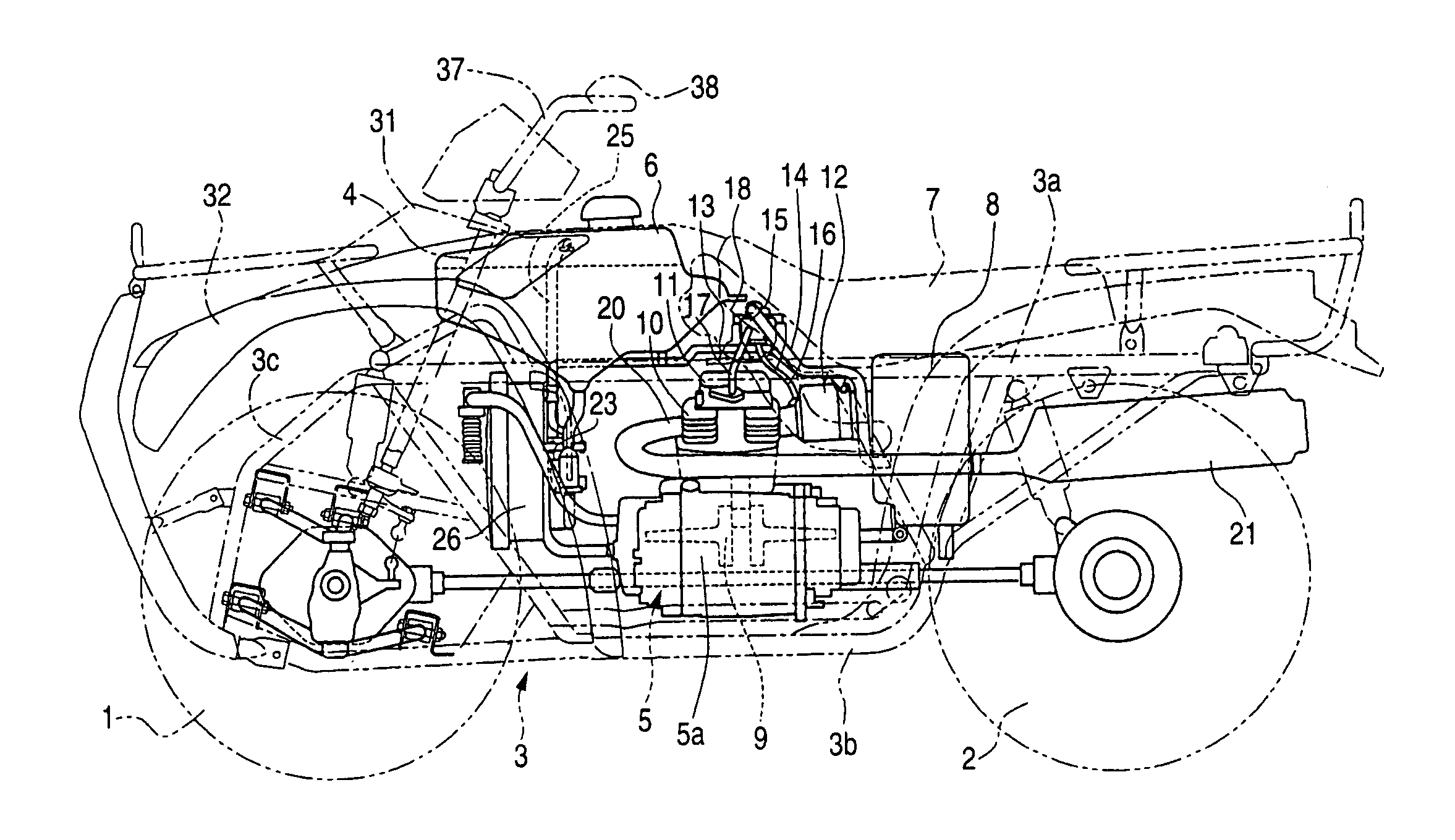
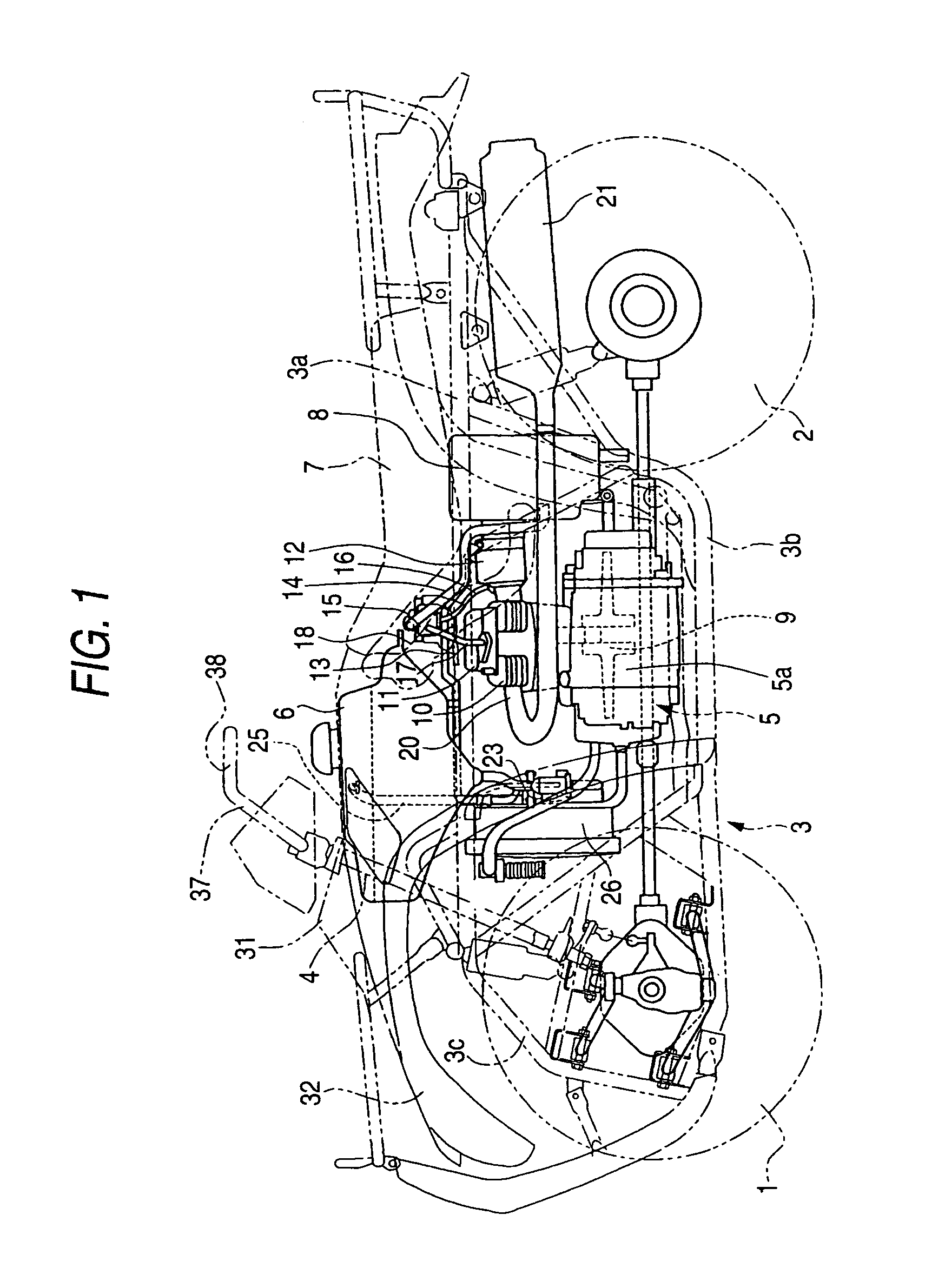
[0043]Hereinafter, an embodiment will be described by reference to the drawings in which the present invention is applied to a 4-wheel buggy, which is a saddle-riding type vehicle. FIG. 1 shows a side view of the 4-wheel buggy. Reference numeral 1 denotes a front wheel, and reference numeral 2 denotes a rear wheel, front wheels and rear wheels being each provided in pair on left and right sides of a vehicle body frame 3. The vehicle body frame 3 has upper frames 3a and lower frames 3b, which are arranged vertically, and the upper frames 3a and the lower frames 3b are each provided in pair in such a manner that the left and right frames extend in a longitudinal direction, the lower frames 3b being connected to the upper frames 3a at front and rear ends thereof. Reference numeral 4 denotes a steering shaft, 5 an engine, 6 a fuel tank, 7 a saddle type seat and 8 an air cleaner.

[0044]The engine 5 is a 4-cycle air-cooled engine and is disposed longitudinally with a crankshaft 9 being dir...


PUM


Abstract

A throttle body is connected to a rear portion of a cylinder head of an air-cooled engine, and a fuel pump is disposed in front of the engine. The fuel pump is such as to be disposed below a fuel tank 6 such a manner as to be separated therefrom and to be integrated with an auxiliary tank. Fuel is sent under pressure from the fuel pump to the throttle body via a fuel feed tube, and surplus fuel is returned to the integrated auxiliary tank, consequently, no piping for return fuel being required. Vapor generated in the fuel 23 returns to a space above a fuel level resulting when the fuel tank 6 is filled up via an exclusive return tube and is, therefore, prevented from mixing into fuel.

Description

[0001]The present invention claims foreign priority to Japanese patent application no. p. 2004-154611, filed on May 25, 2004, the contents of which is incorporated herein by reference.BACKGROUND OF THE INVENTION[0002]1. Field of the Invention[0003]The present invention relates to a vehicle fuel supply construction with a vapor return circuit.[0004]2. Description of the Related Art[0005]In vehicles having a fuel injection system, in order to prevent vapor of fuel generated by a fuel pump from mixing into fuel that is to be injected, a vapor return circuit is provided for separating the vapor from the fuel to return the vapor to a fuel tank.[0006]As an example of such a vapor return circuit, there exists a vapor return circuit in which an injector into which a fuel pump and an injection nozzle are integrated is provided, fuel is supplied from a fuel tank to an auxiliary tank of the injector, and at the same time that fuel is injected by the fuel pump, fuel vapor is returned to the fue...

Claims


Application Information

Patent Timeline
Patent Type & Authority Patents(United States)
IPC IPC(8): F02M37/20B60K15/077B60K15/03B62J37/00F02M37/00F02M37/04
CPCF02M37/0017F02M37/20F02M37/007F02M37/0047
Inventor TSURUTA, YUICHIRO
Owner HONDA MOTOR CO LTD
Why Eureka
Try Eureka