Tension controller and opening-and-closing device for vehicle having the same

a technology of opening and closing device and tension controller, which is applied in the direction of roofs, doors, wing accessories, etc., can solve the problems of slack in the cable fed from the rotary drum, difficult to attach the same type of cable drive unit on both the right and left sliding doors, and difficulty in the attaching operation of the cabl

Inactive Publication Date: 2007-10-30
MITSUI KINZOKU ACT
View PDF15 Cites 17 Cited by
  • Summary
  • Abstract
  • Description
  • Claims
  • Application Information

AI Technical Summary

Benefits of technology

[0010]The object of the present invention is to provide a tension controller having such a structure that a cable is easily connected to an opened-and-closed body, and a small-sized opening and closing device for vehicle having the same.
[0012]According to the present invention, the cable can be easily connected to the opened-and-closed body by moving the abutting member to the second area and then holding it in the engagement portion against the biasing force of the spring when starting to connect the cable to the opened-and-closed body.

Problems solved by technology

Therefore, it is necessary to connect both end portions of the cable to the sliding door while the cable is stretched out against the biasing force of the compression spring, resulting in difficulty in the attaching operation of the cable.
Because of the restriction on its structure, it is difficult to attach the same type of cable drive units on both the right and left sliding doors.
Further, since there is not a tension controller in this device, the slack will occur in the cable fed from the rotary drum.

Method used


Image

  • Tension controller and opening-and-closing device for vehicle having the same
  • Tension controller and opening-and-closing device for vehicle having the same
  • Tension controller and opening-and-closing device for vehicle having the same

Examples


Embodiment Construction

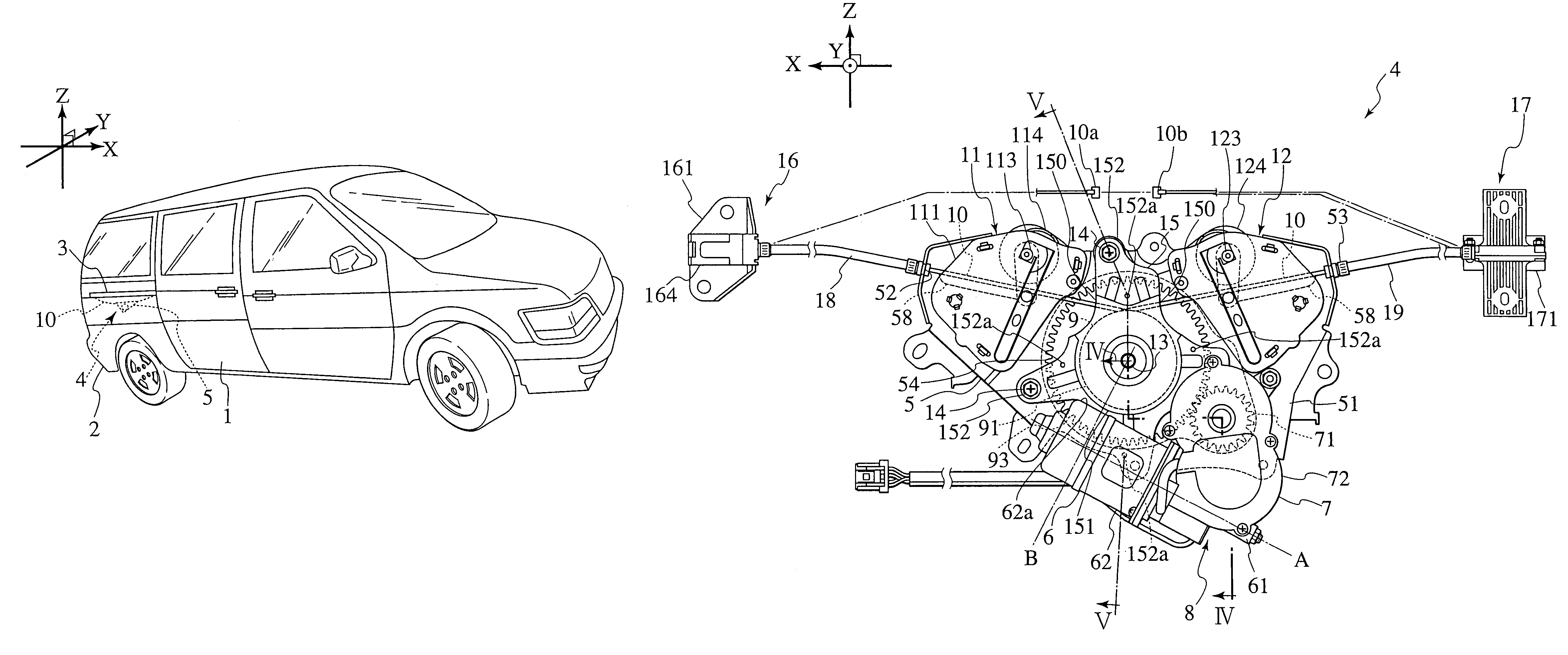
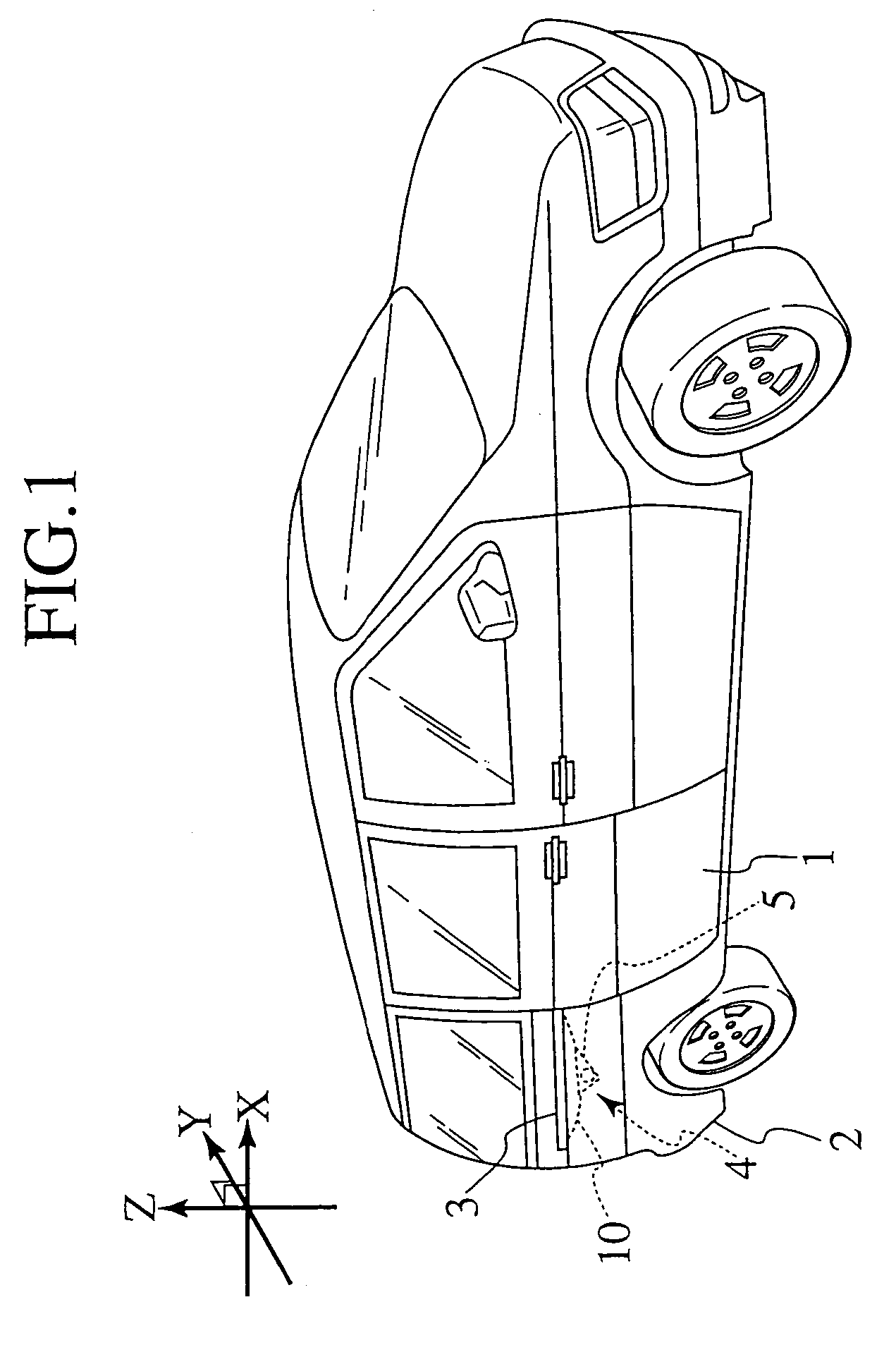
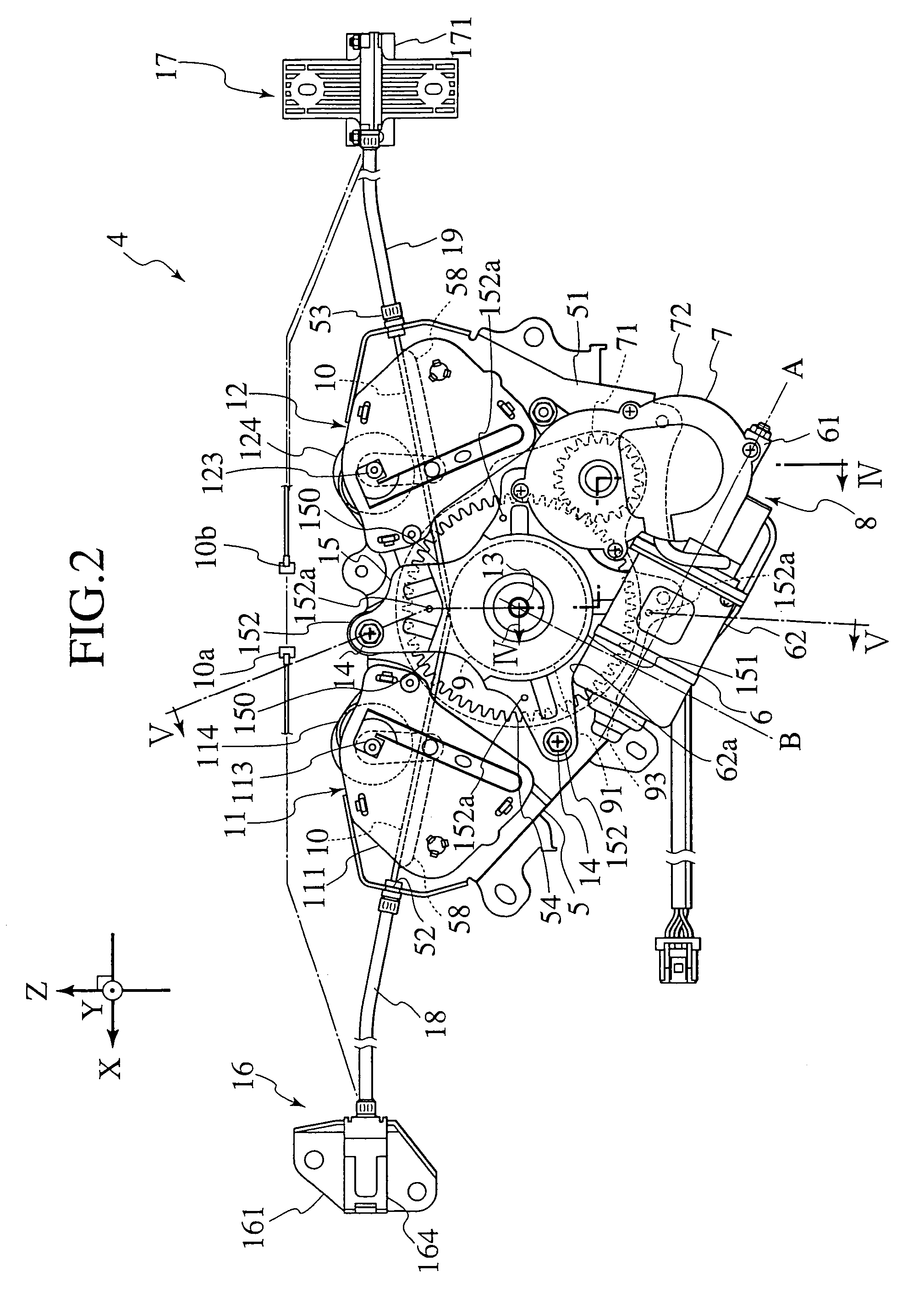
[0034]Referring to FIGS. 1 to 16, an embodiment of the present invention will be described. The longitudinal, lateral and vertical directions of a vehicle are defined as X, Y and Z axes, respectively. The X, Y and Z axes are perpendicular to one another.

[0035]As shown in FIG. 1, a sliding door (an opened-and-closed body) 1 is movably attached to a body panel 2 along the longitudinal direction (X axis). The sliding door 1 is movably supported on an upper rail (not shown in the figure), a lower rail (not shown) and a guide rail 3 which are disposed on an upper end of a door-opening portion, a lower end of the door-opening portion and an external side plate (−Y side) of the body panel 2, respectively. The sliding door 1 is moved by an opening-and-closing device 4 between an entirely closed position (FIG. 1) and an entirely opened position (not shown) along the upper rail, the lower rail and the guide rail 3. The body panel 2 firstly extends toward the exterior (−Y direction) of the veh...


PUM


Abstract

An opening and closing device opens and closes a sliding door by using a cable connected to the sliding door movably attached to a vehicle body. The opening and closing device has a base bracket, a motor, a transmission, a rotary drum, a first conduit fixed portion, a second conduit fixed portion, a first tension controller and a second tension controller. The base bracket is fixed to the vehicle body with bolts. The motor, the transmission, the rotary drum, the first and second conduit fixed portions and the first and second tension controllers are fixed to a disposition face of the base bracket. The first and second tension controllers are respectively disposed between the rotary drum and the first conduit fixed portion and between the rotary drum and the second conduit fixed portion, and applies tension to the cable fed from the rotary drum to take up the slack.

Description

CROSS REFERENCE TO RELATED APPLICATION [0001]This application claims benefit of priority under 35 U.S.C. § 119 to Japanese Patent Application No. 2003-096363 filed on Mar. 31, 2003 and Japanese Patent Application No. 2003-145338 filed on May 22, 2003, the entire contents of which are incorporated by reference herein.BACKGROUND OF THE INVENTION [0002]1. Field of the Invention[0003]The present invention relates to a tension controller for applying tension to a cable used to move an opened-and-closed body attached to a vehicle body and also relates to an opening and closing device for vehicle having the same.[0004]2. Description of the Related Art[0005]An opening and closing device for vehicle has been disclosed in Japanese Patent Provisional Publication No.9-256732. In the opening and closing device for vehicle, a cable has a central portion to be wound around a rotary drum and both end portions to be connected to a sliding door. The cable is passed through flexible conduits in the vi...

Claims


Application Information

Patent Timeline
Patent Type & Authority Patents(United States)
IPC IPC(8): B60J5/06E05F15/14
CPCE05F15/646E05Y2201/654E05Y2201/664E05Y2201/668E05Y2201/672E05Y2600/13E05Y2600/32E05Y2800/21E05Y2900/531E05Y2201/484E05Y2600/31
Inventor YAMAGISHI, JUNKITA, SHINICHIRO
Owner MITSUI KINZOKU ACT
Why Eureka
Try Eureka