Construction machine

a construction machine and floor panel technology, applied in soil shifting machines/dredgers, roofs, transportation and packaging, etc., can solve the problems of troublesome and time-consuming tilt-up operation of the floor panel, difficult to secure a the swing motor or other equipment, and the difficulty of ensuring the space for installation of the control valve, etc., to achieve easy tilt-up operation and simple and convenient manner.

Inactive Publication Date: 2007-10-30
NIHON KENKI CO LTD
View PDF7 Cites 22 Cited by
  • Summary
  • Abstract
  • Description
  • Claims
  • Application Information

AI Technical Summary

Benefits of technology

[0014]In view of the above-discussed problems with the prior art, it is an object of the present invention to provide a construction machine which is so arranged as to make a rear side portion of a floor panel disconnectable from a frame in a simple and facilitated manner, permitting to tilt up the floor panel easily at the time of maintenance and service of equipments.
[0015]It is another object of the present invention to provide a construction machine which is so arranged to prevent overloading of a tilting mechanism when a floor panel is tilted up in a forward direction, improving the durability and prolonging the service life of the tilting mechanism while ensuring stabilized tilt-up actions of the floor panel.

Problems solved by technology

In the case of small-size hydraulic excavators, it is difficult to secure a space for installation of a control valve, a swing motor or other equipments.
This means that it takes a great deal of time and labor just for dismantling the vibration insulating members, making a tilt-up operation of the floor panel troublesome and time consuming.
Besides, as described above, at the time of lifting a rear side of the floor panel to tilt up the whole floor panel in forward direction together with an operator's seat and a housing, the center of gravity is shifted by the tilt-up operation, giving rise to a problems as described below.
However, as the tilt-up angle of the floor panel increases, the center of gravity is shifted to a position forward of a supporting point on the floor panel support mechanism, and as a result, the loads of the floor panel, operator's seat and housing act to become a reversal force which tends to push up the rear side of the floor panel.
As a consequence, in the case of a tilting mechanism using gas dampers or the like, as the tilt-up angle of the floor panel increases, loads of the floor panel, operator's seat and housing inversely act as a pulling force, imposing a great load on gas dampers to such a degree as to cause premature damages to the gas dampers, deteriorating their durability and the service life.

Method used


Image

  • Construction machine
  • Construction machine
  • Construction machine

Examples


first embodiment

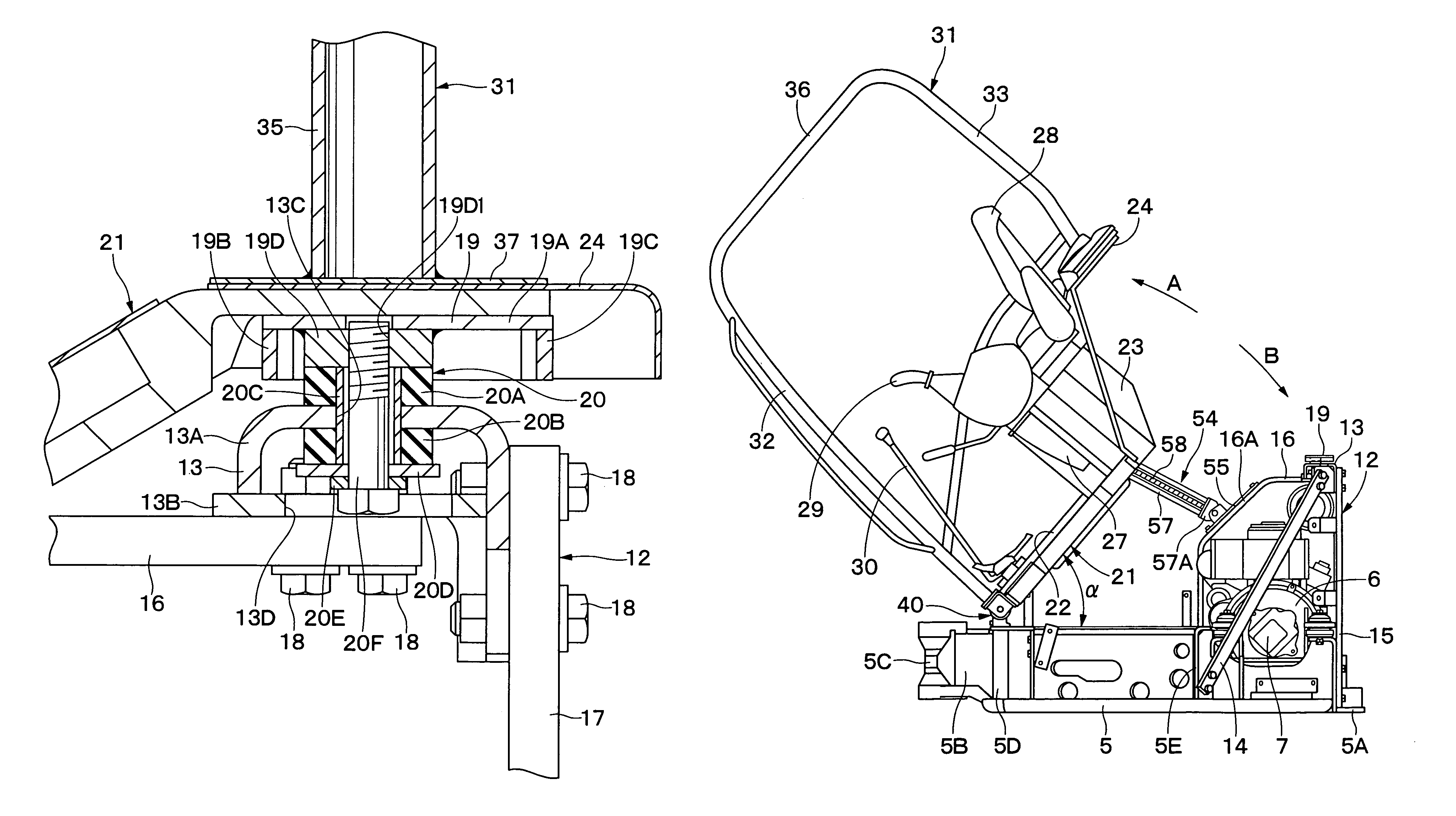
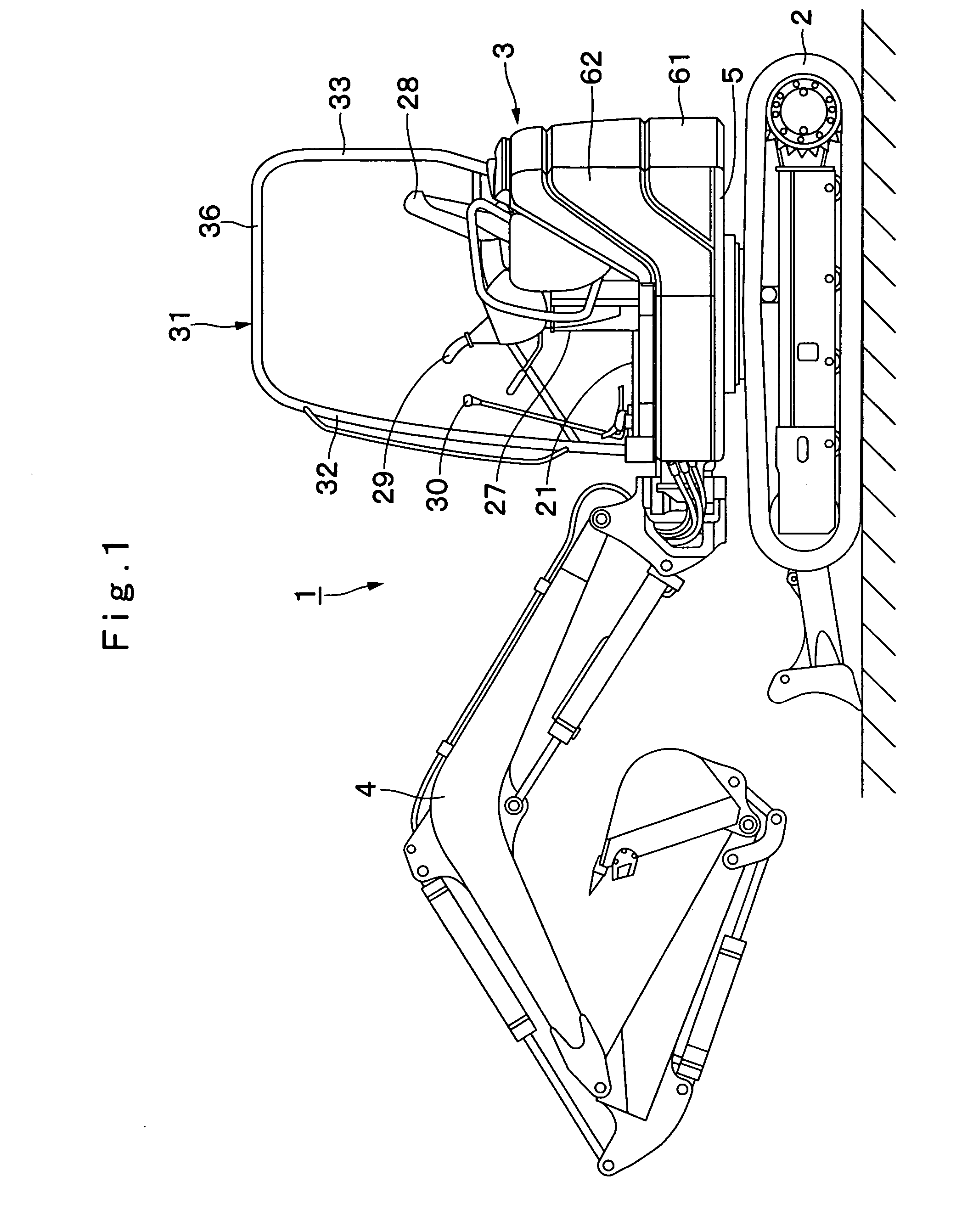
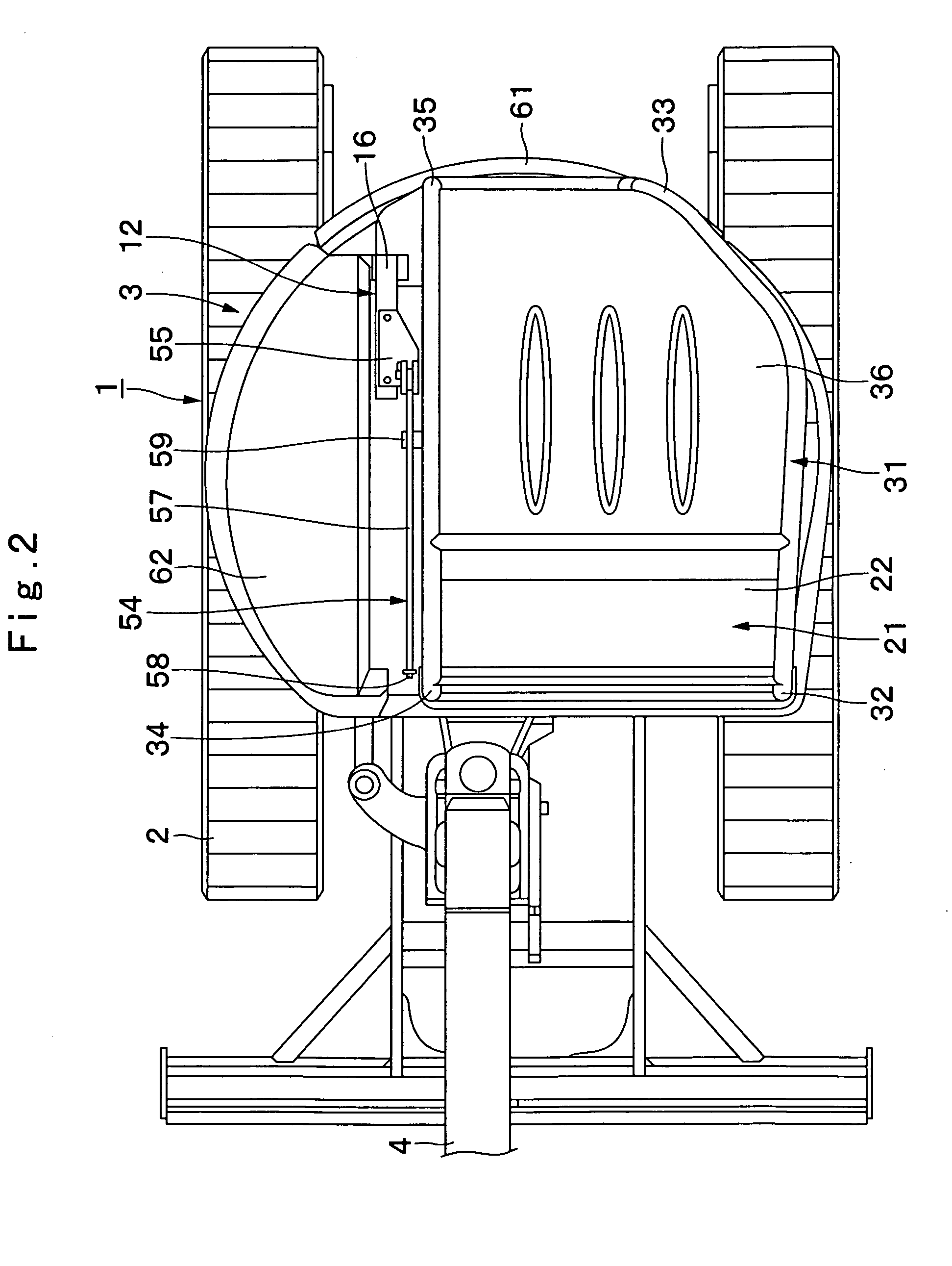
[0070]Shown in FIGS. 1 through 23 is the construction machine according to the present invention.

[0071]In the drawings, indicated at 1 is a canopy type hydraulic excavator as a construction machine. The hydraulic excavator 1 is constituted by a crawler type automotive lower structure 2, and an upper revolving structure 3 which is rotatably mounted on the lower structure 2. Rotatably provided on the front side of the upper revolving structure 3 is a swing type working machine 4, for example, for ground excavating operations.

[0072]When seen from above, the upper revolving structure 3 is formed substantially in a circular shape (see FIG. 2), so that it can be turned within the width of the lower structure 2. Further, as shown in FIGS. 1 through 6, the upper revolving structure 3 is largely constituted by revolving frame 5, engine 6, support member 12, floor panel mount plate 19, vibration insulators 20, floor panel 21, operator's seat 28, canopy 31, fastening bolts 39, floor panel supp...

second embodiment

[0170]In the above-described second embodiment, by way of example the support pins 72 and stopper pins 73 are employed as fastening members for detachably fixing the housing mount plate 24 of the floor panel 21 to the floor panel mount plate 71. However, in this regard, the present invention is not limited to the particular examples shown. For instance, a nut may be employed as a stopper member and threaded onto a male screw which is tapped at and around an upper end of each one of the support pins 72 as shown in FIG. 24.

[0171]Further, in the first embodiment, the housing mount plate 24 of the floor panel 21 is fixed to the floor panel mount plate 19 by the use of three fastening bolts 39. However, the present invention is not limited to this particular example. Namely, the housing mount plate 24 of the floor panel 21 may be fixed to the floor panel mount plate 19 by the use of two or more than four fastening bolts 39.

[0172]Further, in the first embodiment, by way of example a total...


PUM


Abstract

Right and left floor panel support mechanisms (40) and (46) are provided on a revolving frame (5) to support a front end of a floor panel (21) pivotally for permitting tilt-up and tilt-down of the floor panel (21). A tilting mechanism (54) is provided between the revolving frame (5) and the floor panel (21) for tilting the floor panel (21) together with a canopy (31). Through a plural number of vibration insulators (20), a floor panel mount plate (19) is mounted on a support member (12) which is located in a rear side portion of the revolving frame (5). A housing mount plate (24) of the floor panel (21) and a base plate (37) of the canopy (31) are detachably fixed to the floor panel mount plate (19) by the use of fastening bolts (39). After removing the fastening bolts (39), the floor panel (21) and canopy (31) can be tilted together without necessitating to disassemble the vibration insulators (20).

Description

TECHNICAL FIELD[0001]This invention relates to construction machines such as, for example, hydraulic excavators and hydraulic cranes, and more particularly to a construction machine with a floor panel which is tiltable relative to a frame of the machine.BACKGROUND ART[0002]Generally, as a construction machine, a hydraulic excavator is constituted by an automotive lower structure, an upper revolving structure which is rotatably mounted on the automotive lower structure, and a working mechanism rotatably mounted on a front side section of the upper revolving structure.[0003]Normally, the upper revolving structure on a hydraulic excavator of this sort is largely constituted by a revolving frame, an engine which is mounted on a rear side section of the revolving frame, a counterweight which is attached to rear end of the revolving frame at a position on the rear side of the engine, a floor panel which is provided on the revolving frame at a position on the front side of the engine, an o...

Claims


Application Information

Patent Timeline
Patent Type & Authority Patents(United States)
IPC IPC(8): B62D33/067B62D33/10B62D33/06
CPCB62D33/0604B62D33/0617E02F9/166E02F3/325E02F9/0891B62D33/067
Inventor ISHII, HAJIMEKIMURA, SHOGOHIRASAWA, SHIGERUTANAKA, TOMOYUKITABETA, HIROSHI
Owner NIHON KENKI CO LTD
Why Eureka
Try Eureka