Vibration absorber with dynamic damper

a technology of vibration absorber and damper, which is applied in the direction of shock absorbers, machine supports, mechanical equipment, etc., can solve the problems of inability to ensure a sufficiently large size of the damper weight, inability to secure the space between the parts, and uncomfortable shock, etc., to achieve less variable spring rate, and convenient adjustment of the spring rate of the entire stopper rubber

Inactive Publication Date: 2007-11-06
KURASHIKI KAKO CO LTD
View PDF32 Cites 18 Cited by
  • Summary
  • Abstract
  • Description
  • Claims
  • Application Information

AI Technical Summary

Benefits of technology

[0012]The present invention has been made in view of the above points, and its object is therefore to ensure a necessary mass for a damper weight of a dynamic damper disposed at one axial end of a cylindrical vibration absorber while saving space by contriving the structure of the dynamic damper and prevent an uncomfortable shock from occurring when a stopper works.
[0027]Furthermore, when a circumferential spiral groove is formed in the outer periphery of the stopper rubber or the damper weight is made of metal, this facilitates the tuning of the spring rate of the entire stopper rubber and provides the effects due to the tuning with stability.

Problems solved by technology

H04-4541), a problem arises with how the dynamic damper coexists at the one axial end with the stopper rubber which should usually be disposed at that site.
Even if various attempts are made to axially juxtapose these parts, space for both parts cannot be secured in many cases.
In this case, however, the following problem will arise.
When the damper weight in the stopper rubber impacts a counter stopper member (also made of metal in many cases) through the thin rubber layer of the stopper rubber, an uncomfortable shock will occur.
This invites a space problem as described above, or makes it impossible that the damper weight ensures a sufficiently great size, which fails to ensure a necessary mass to provide the intrinsic damping effect of the dynamic damper.

Method used


Image

  • Vibration absorber with dynamic damper
  • Vibration absorber with dynamic damper
  • Vibration absorber with dynamic damper

Examples


Embodiment Construction

[0037]Embodiments of the present invention will be described below in detail with reference to the drawings. The following description of the preferred embodiments is merely illustrative in nature and is not intended to limit the scope, applications and use of the invention.

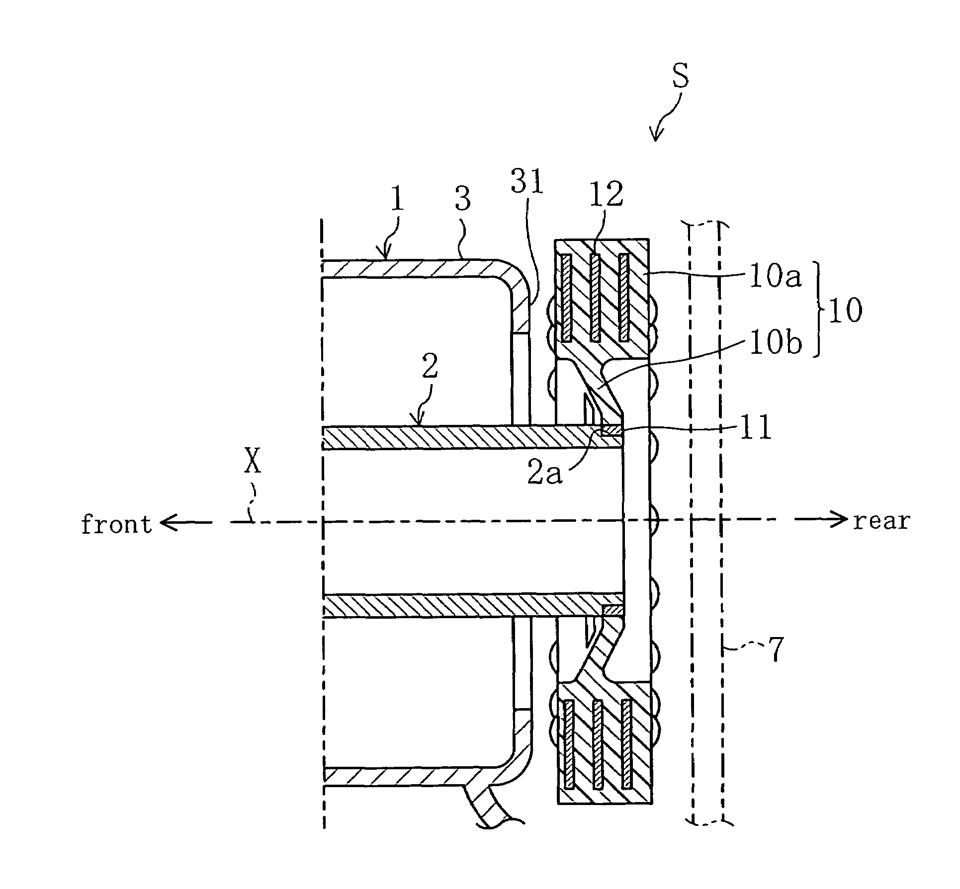
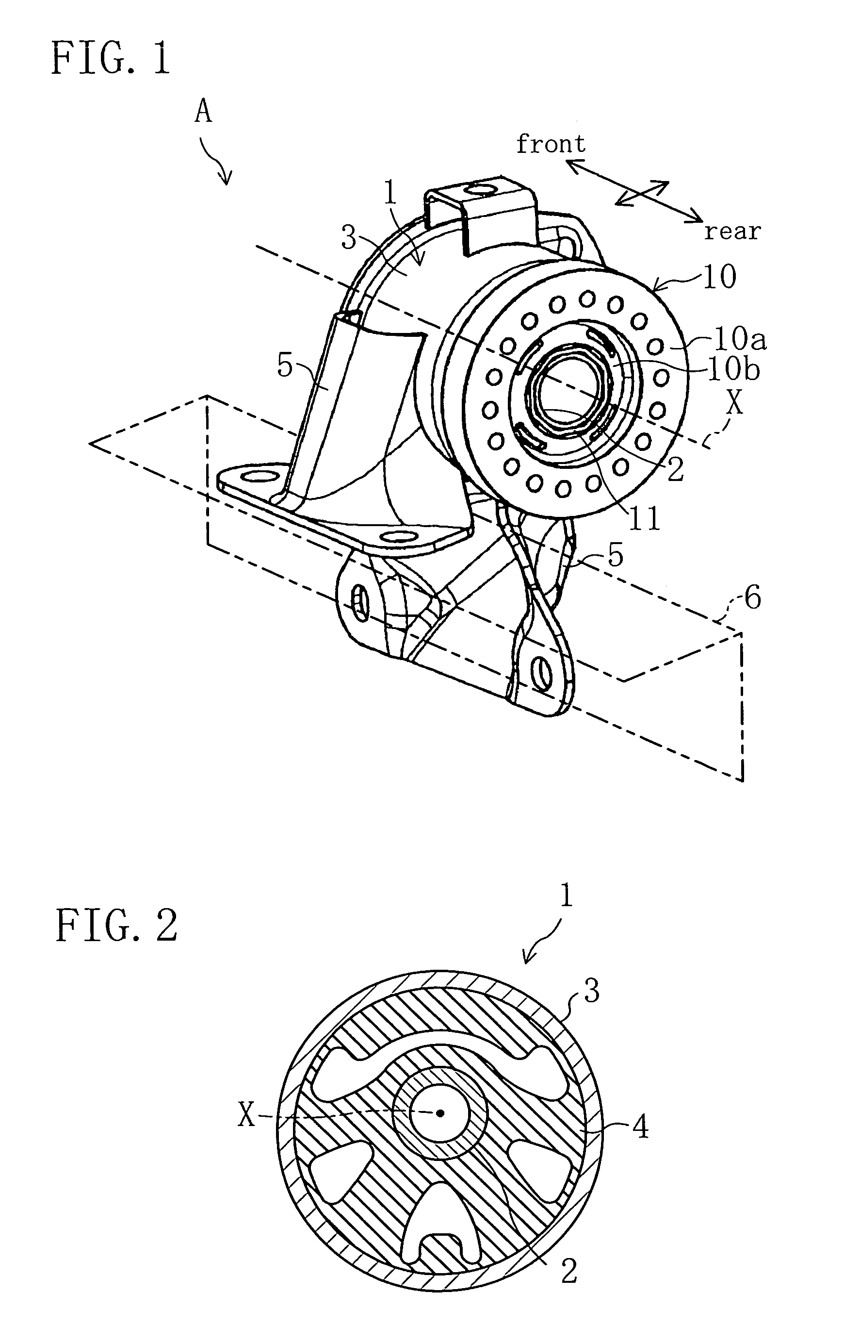
[0038]FIGS. 1 and 2 show an embodiment in which a vibration absorber according to the invention is applied to an engine mount A for a vehicle. The engine mount A is interposed between an unshown vehicle power plant and a vehicle body and functions to support the load of the power plant and restrain the transmission of vibrations from the power plant to the vehicle body by absorbing or attenuating the vibrations from the power plant.

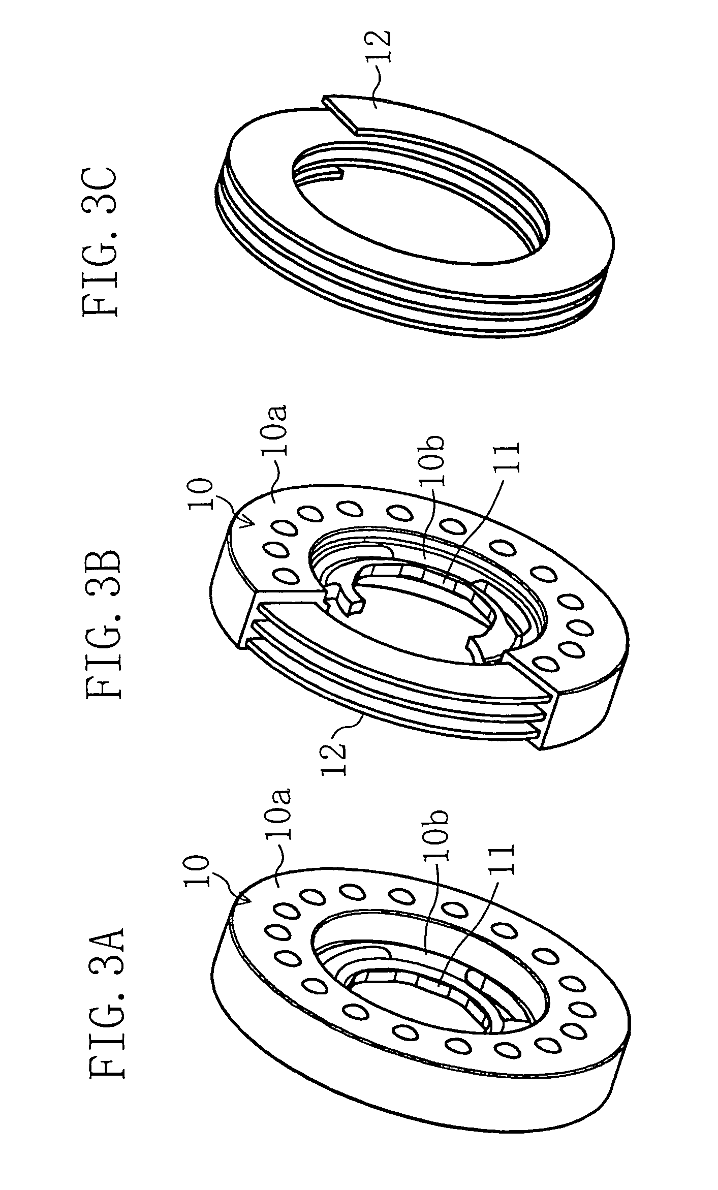
[0039]To be more specific, as shown in the transverse cross section in FIG. 2, a body 1 of the engine mount A of this embodiment is constructed so that inner and outer cylinders 2 and 3 are connected through a rubber elastic element 4. As shown in FIG. 1, the outer cylinder 3 is connec...


PUM


Abstract

In an engine mount (A) whose axis (X) is oriented in the front to rear direction of a vehicle, a damper weight (12) is embedded within a toroidal stopper rubber (10) fixed at its inner periphery to the rear end of an inner cylinder (2). The damper weight (12) is made of, for example, steel plate to have a spiral form and placed to surround the inner cylinder (2), thereby itself functioning as a spring in the direction of the axis (X). This structure can ensure a necessary mass for the damper weight while saving space, and prevent the occurrence of an uncomfortable shock when a stopper works.

Description

CROSS-REFERENCES TO RELATED APPLICATIONS[0001]This application claims priority under 35 USC 119 to Japanese Patent Application No. 2005-83495, filed on Mar. 23, 2005, the entire contents of which are incorporated herein by reference.BACKGROUND OF THE INVENTION[0002](a) Field of the Invention[0003]This invention relates to cylindrical vibration absorbers mainly used as an engine mount or a suspension bush, and particularly relates to the technical filed of structures of cylindrical vibration absorbers with a dynamic dumper.[0004](b) Description of the Related Art[0005]As an example of vibration absorbers of this kind, a vibration absorber is known which is formed by connecting inner and outer cylinders through an elastic element and in which a stopper mechanism for restricting relative axial movement of the inner and outer cylinders is provided at least at one axial end of the vibration absorber and a stopper rubber is placed for cushioning the shock caused by the action of the stopp...

Claims


Application Information

Patent Timeline
Patent Type & Authority Patents(United States)
IPC IPC(8): F16F7/10
CPCF16F1/3814F16F7/104F16F3/12F16F2230/007
Inventor MIYAKE, KAZUO
Owner KURASHIKI KAKO CO LTD
Why Eureka
Try Eureka