
Recording tape cartridge

a technology for recording tapes and cartridges, applied in the field of recording tape cartridges, can solve the problems of abrasion powder generation, case scratching, and tilting with respect, and achieve the effect of preventing the positional offset of the cas

Inactive Publication Date: 2007-11-06
FUJIFILM CORP +1
View PDF16 Cites 0 Cited by
  • Summary
  • Abstract
  • Description
  • Claims
  • Application Information

AI Technical Summary

Benefits of technology

[0014]In view of the aforementioned, an object of the present invention is to provide a recording tape cartridge which can prevent positional offset of a case with regard to a cartridge accommodating device.

Problems solved by technology

However, in the above-described conventional recording tape cartridge, when the operation portion of the door engages the opening / closing member of the drive device at the time of opening the opening, a rotational moment around the region of this engagement arises, and a problem arises in that the case (i.e., the recording tape cartridge) rotates around this region of engagement and becomes tilted with respect to the direction of loading.
If the case is pushed into the drive device in this state, there is the concern that the case will rub against the interior of the drive device, and the case will become scratched or abrasion powder will be generated within the drive device, or the case will become stuck within the drive device.
However, in a case which is formed by joining together an upper case and a lower case molded of a resin material as described above, the outer surface which includes the aforementioned front surface is a design surface at which crimping processing and the like are carried out, and the draft for removing the case from a mold after molding is large and the dimensional accuracy is low.
Moreover, with an anchor means which anchors the case after the opening has been opened, the aforementioned rotational moment cannot be offset.

Method used


Image

  • Recording tape cartridge
  • Recording tape cartridge
  • Recording tape cartridge

Examples


Embodiment Construction

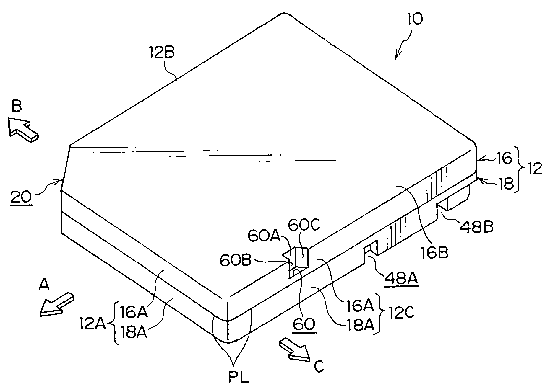
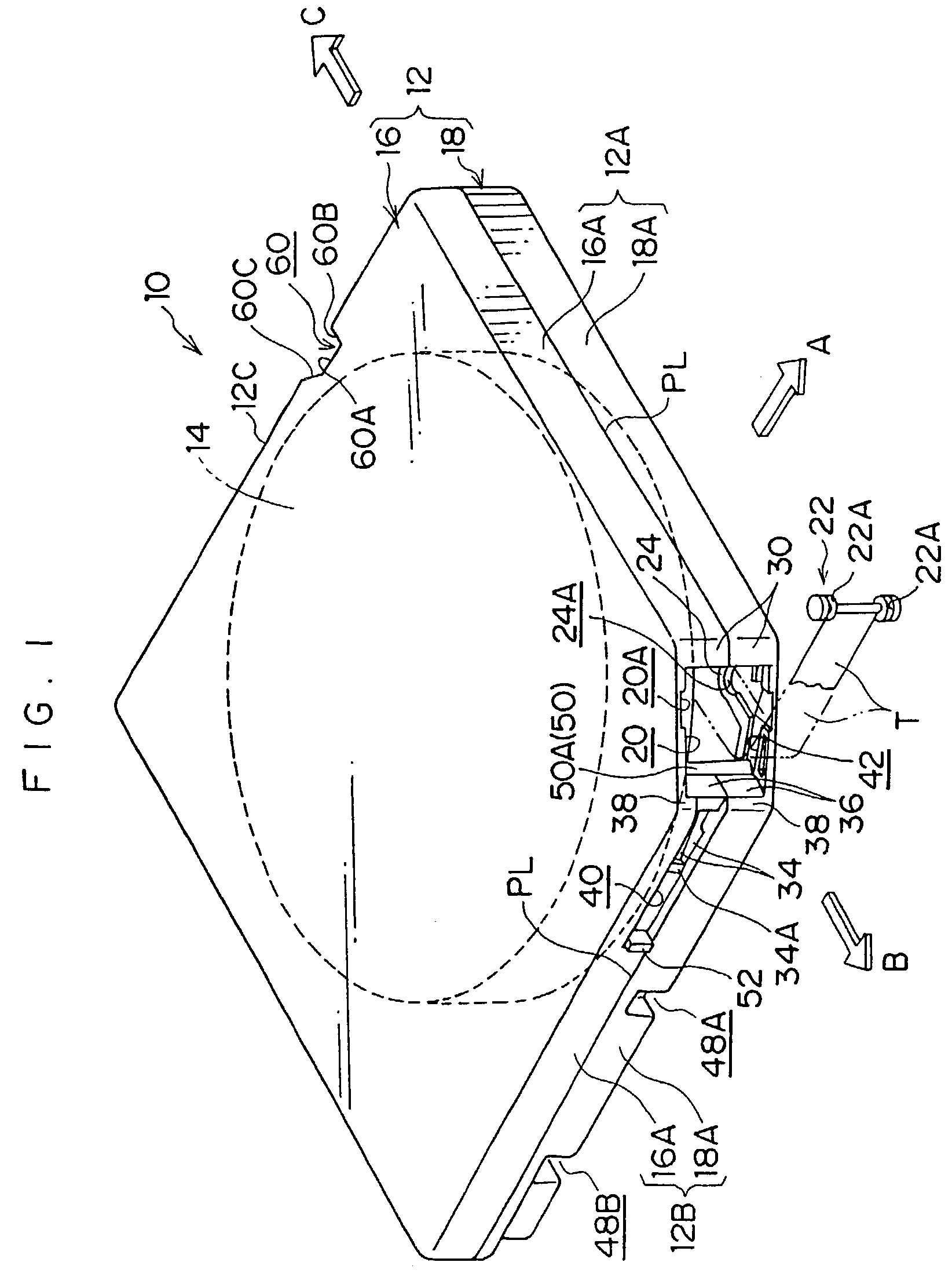
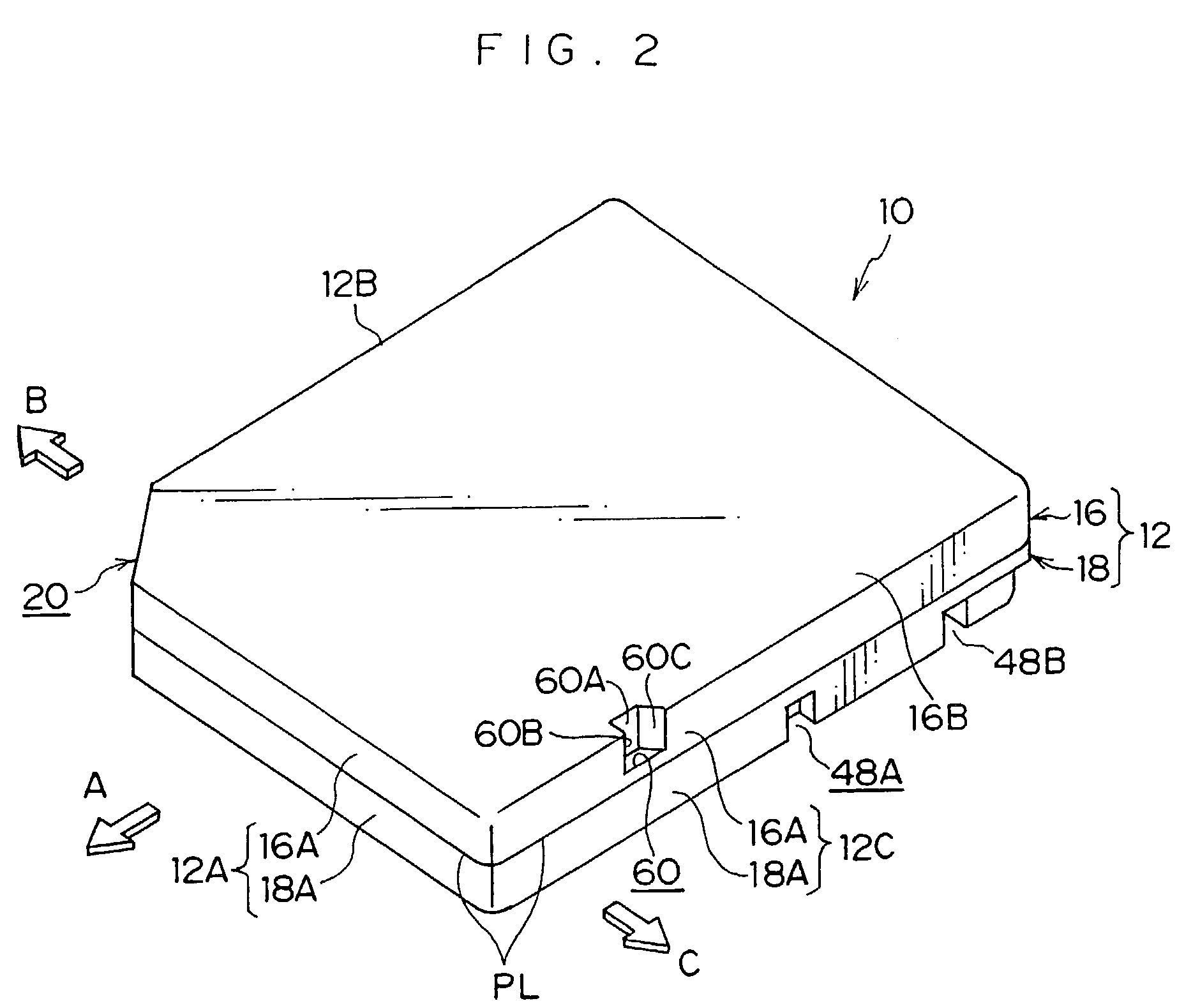
[0030]Hereinafter, a recording tape cartridge 10 relating to an embodiment of the present invention will be described on the basis of FIGS. 1 through 10. First, the basic overall structure of the recording tape cartridge 10 will be described. Then, an opening, a door which serves as a shielding member, and a cell retention notch 60 serving as a concave portion which is a main portion of the present invention, will be described. Note that, for convenience of explanation, the direction of loading the recording tape cartridge 10 into a drive device, which is denoted by arrow A, is the forward direction (front side) of the recording tape cartridge 10. The directions of arrow B and arrow C, which are orthogonal to the direction of arrow A, are the rightward direction and the leftward direction, respectively.

(Overall Structure of Recording Tape Cartridge)

[0031]The overall structure of the recording tape cartridge 10 is shown in perspective views in FIGS. 1 and 2, and a schematic exploded ...


PUM

PropertyMeasurementUnit
heightaaaaaaaaaa
heightaaaaaaaaaa
outer diameteraaaaaaaaaa

Abstract

A recording tape cartridge which can prevent positional offset of a case with respect to a cartridge accommodating device. Accompanying operation of loading the cartridge in an arrow A direction into a drive device, a door is moved to a side of opening an opening while an operation projection is engaged by an engagement projection. At this time, a pushing / engaging member of the drive device enters into a cell retention notch, and pushes a push surface and engages with an engagement surface. In this way, at the case, a moment in an arrow E direction around a region of engagement is offset, and the case is prevented from being coming out from the drive device. An inclined surface permits advance and withdrawal of the pushing / engaging member into and from the notch.

Description

BACKGROUND OF THE INVENTION[0001]1. Field of the Invention[0002]The present invention relates to a recording tape cartridge which rotatably accommodates a reel on which a recording tape, such as a magnetic tape or the like, is wound.[0003]2. Description of the Related Art[0004]Recording tapes, such as magnetic tapes and the like, are used as external recording media for computers and the like. Recording tape cartridges are used which accommodate a single reel on which is wound a recording tape which requires little space for storage and on which a large amount of information can be recorded. In a recording tape cartridge, a single reel on which a recording tape is wound is rotatably accommodated within a case which is formed by joining together an upper case and a lower case which are molded of a resin material. An opening is formed in the case. The recording tape is pulled-out from this opening, and is taken-up onto a take-up reel of a drive device.[0005]The opening is opened and c...

Claims


Application Information

Patent Timeline
Patent Type & Authority Patents(United States)
IPC IPC(8): G11B23/07G11B23/107
CPCG11B23/107
Inventor HIRAGUCHI, KAZUO
Owner FUJIFILM CORP
Learn More