Hydraulic vehicle seat adjustment system

a technology for vehicle seats and adjustment systems, applied in the direction of vehicle seats, vehicle components, movable seats, etc., can solve the problems of increasing assembly costs, increasing complexity, and increasing complexity, and achieve the effect of reducing costs and duplication of components

Active Publication Date: 2007-11-06
LEAR CORP
View PDF33 Cites 15 Cited by
  • Summary
  • Abstract
  • Description
  • Claims
  • Application Information

AI Technical Summary

Benefits of technology

[0014]This arrangement provides a relatively simple and cost effective means to determine the position of multiple hydraulically adjusted seat adjustments. In particular costs, complexity, wiring and pipework are reduced and simplified by utilising only a single common flow sensor for the multiple adjustments. Furthermore a single flow sensor comprises a relatively simple sensor means for measuring the seat position as compared to some other types of position sensor arrangements.
[0019]Utilising a common source of pressurised hydraulic fluid reduces the costs and duplication of components required to provide powered positional adjustment of multiple seat adjustments.

Problems solved by technology

In spite of this hydraulic adjustment arrangements have not been widely adopted principally due to perceived complexity and high cost.
This undesirably adds to the complexity of the seat and seat control system with the additional sensor arrangements and additional wiring increasing costs, making assembly more difficult and costly, and possibly also increasing reliability problems with their being further scope for failure of the multiple individual sensor arrangements.
Furthermore with hydraulic powered systems direct seat position measurement arrangements are typically required to for example measure the extension of the respective hydraulic cylinder actuators, or seat adjustment itself, which can be relatively complex, costly, and are susceptible to damage.

Method used


Image

  • Hydraulic vehicle seat adjustment system
  • Hydraulic vehicle seat adjustment system
  • Hydraulic vehicle seat adjustment system

Examples


Embodiment Construction

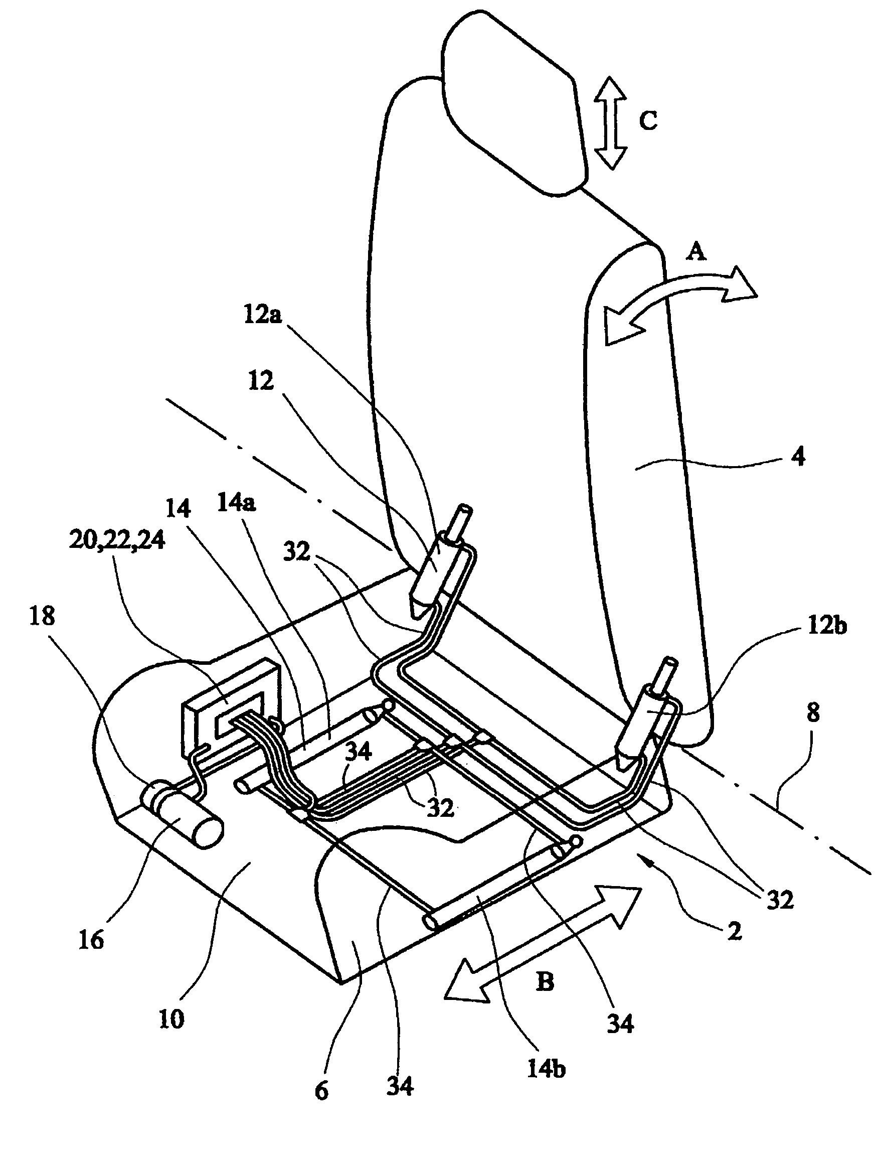
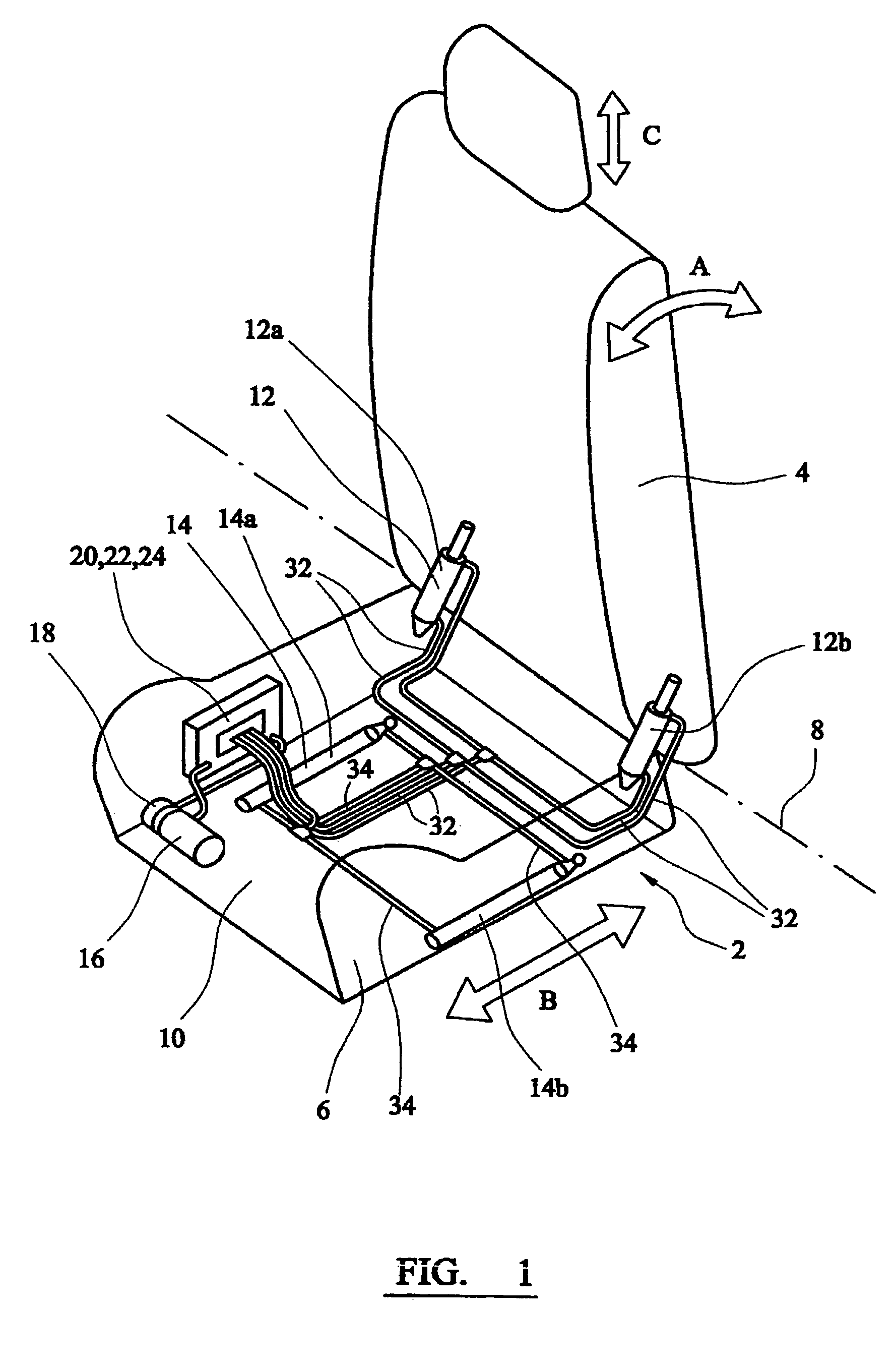
[0023]Referring to FIG. 1 there is shown a schematic illustration of the disposition of a hydraulically powered seat adjustment system 10 within an outline of an automotive vehicle seat 2.

[0024]The vehicle seat 2 includes a seat back 4 which is pivotally connected to a bottom seat cushion 6, in a conventional manner, at one end about a horizontal lateral axis 8. The angle of the seat back 4 can accordingly be adjusted relative to the generally horizontally disposed seat bottom cushion 6 as indicated by arrow A. A pair of seat pivot hydraulic actuators 12a,12b, one on each lateral side of the seat 2, are operatively connected between the seat back 4 and seat bottom cushion 6 to adjust, control, and set the angle of the seat back 4.

[0025]The seat bottom cushion 6 is slidably mounted to the vehicle floor (not shown) in a conventional manner, for example using a pair of sliding seat tracks or rail assemblies (not shown). This allows the seat bottom cushion 6 and seat 2 to be slid fore a...


PUM


Abstract

A hydraulic vehicle seat adjustment system for providing positional adjustment of at least two seat adjustments of a vehicle seat. The system comprises a common source of hydraulic fluid, and a control unit which selectively controls and directs hydraulic fluid from the common source of hydraulic fluid to respective first and second actuators to adjust the respective different seat adjustments, for example fore and aft position of the seat, and seat back angle. The system may further also comprise a seat position determining unit connected to the control unit and to a common fluid flow sensor to determine the flow of hydraulic fluid from the common source of hydraulic fluid to the respective first and second actuators and to thereby determine the adjusted position of the respective actuators and so of the respective seat adjustment.

Description

CROSS REFERENCE TO RELATED APPLICATIONS[0001]This application claims priority to Great Britain Patent Application No. 0328942.8 filed Dec. 15, 2003, the disclosures of which are incorporated herein by reference; Great Britain Patent Application No. 0324552.9 filed Oct. 22, 2003, the disclosures of which are incorporated herein by reference; Great Britain Patent Application No. 0324558.6 filed Oct. 22, 2003, the disclosures of which are incorporated herein by reference; and Great Britain Patent Application No. 0328724.0 filed Dec. 10, 2003, the disclosures of which are incorporated herein by reference.BACKGROUND OF THE INVENTION[0002]The present invention relates to adjustable vehicle seats, in particular hydraulically adjustable automotive vehicle seats, and to determining the position of the adjusted vehicle seat.[0003]In order to comfortably accommodate various sizes and shapes of occupants vehicle seats are generally provided with various adjustment mechanisms to adjust the posit...

Claims


Application Information

Patent Timeline
Patent Type & Authority Patents(United States)
IPC IPC(8): B60N2/02B60N2/06B60N2/12B60N2/23B60N2/48
CPCB60N2/02B60N2/4829B60N2/231B60N2/067B60N2/829
Inventor CHRISTOPHER, HUGH H.
Owner LEAR CORP
Why Eureka
Try Eureka