Illuminating system and method for improving asymmetric projection

a technology of asymmetric projection and illumination system, which is applied in the field of projection system, can solve the problems of decreasing illumination efficiency, and achieve the effects of improving illumination efficiency, increasing contrast, and improving asymmetric light spo

Inactive Publication Date: 2007-11-06
YOUNG OPTICS
View PDF12 Cites 10 Cited by
  • Summary
  • Abstract
  • Description
  • Claims
  • Application Information

AI Technical Summary

Benefits of technology

[0011]One objective of the present invention is to provide a method for offsetting two asymmetric diagonals of the distorted light spot. By the use of an anamorphic surface unit of a projection system, the method will improves the asymmetric light spot resulted from the inclined incidence to achieve a more symmetric light spot.
[0012]The other objective of the present invention is to use an anamorphic surface unit for producing two asymmetric orthogonal axes so that an illuminating system can generate a parabolic-sectional light beam with a smaller F-number. Thus, that can avoid the overlap of light beams between on-state and flat-state to raise the contrast. Furthermore, by amplifying the light spot, the projection system will increase the total illumination efficiency of the optic system.

Problems solved by technology

The above-mentioned prior art has at least two drawbacks as follows: one reduces the uniform brightness of the light spot resulted from the unequal extension of two diagonals; the other causes the brightness loss on circumference of the light spot from the extension of the first diagonal L1 out of the light valve and results in decreasing the illumination efficiency.

Method used


Image

  • Illuminating system and method for improving asymmetric projection
  • Illuminating system and method for improving asymmetric projection
  • Illuminating system and method for improving asymmetric projection

Examples


Embodiment Construction

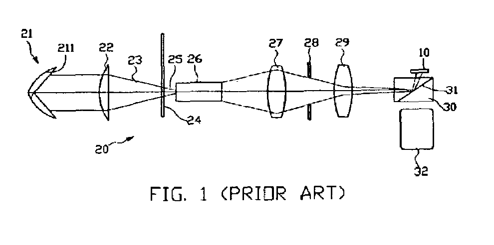
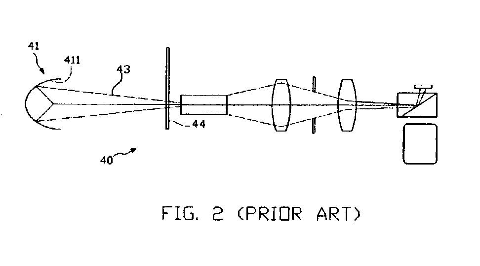
[0025]Referring to the drawings, the present invention will be described in a following embodiment. For solving a distortion of the prior art, the present invention is to provide an anamorphic surface unit for offsetting the distortion formed by two asymmetric diagonals of a light spot, so that the asymmetric light spot, resulting from inclined incidence of a projection system, can be improved into a more symmetric light spot.

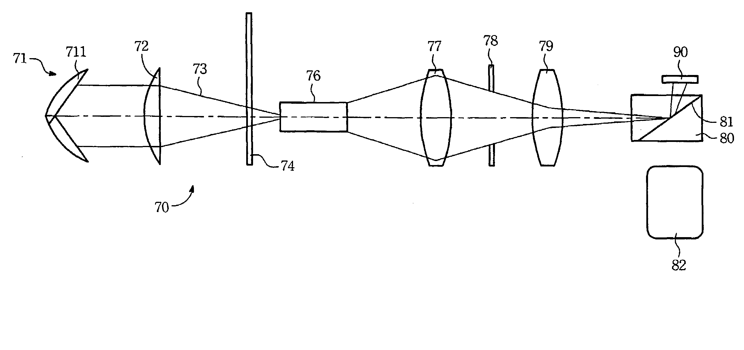
[0026]Referring to FIG. 11, an embodiment of the invention has almost the same projection system and light path as the first projection system 70 of the prior art, but there is a difference in the relay lens 79. That is, the embodiment of the invention, the system for improving asymmetric projection 70, includes the light source 71 producing a light beam 73 to form a light path. The light beam 73 successively passes through the reflector 711, the converging lens 72, the color wheel 74, integration rod 76, the condenser lens 77, the stop 78, the relay lens 79, t...


PUM

PropertyMeasurementUnit
axial lengthaaaaaaaaaa
lengthaaaaaaaaaa
brightnessaaaaaaaaaa

Abstract

An illuminating system and method for improving asymmetric projection includes a light source producing a light beam to form a light path, a projection lens disposed in the light path, a light valve inserted in the light path between the light source and the projection lens, and at least one anamorphic surface unit placed in the light path between the light source and the light valve. The anamorphic surface unit offsets a distortion of a light spot resulted from obliquely incidence on the light valve, thus an asymmetric light spot can be improved as a more symmetric one to increase illuminating collection efficiency and uniformity.

Description

CROSS REFERENCE TO RELATED APPLICATION[0001]This application incorporates by reference Taiwanese application Serial No. 90128276, filed on Nov. 15, 2001.BACKGROUND OF THE INVENTION[0002]1. Field of the Invention[0003]The present invention relates to a projection system and, more particularly, to an illuminating system and method for improving asymmetric projection in a projection system.[0004]2. Description of Related Art[0005]Referring to FIG. 1, a projection system 20 in a prior art is a single panel full color system having a light source 21 with a parabolic concave reflector 211 to emit a white light beam 23. After reflected by the parabolic concave reflector 211, the white light beam 23 passes through a converging lens 22 to converge the light beam 23 on a color wheel 24. When rotating around a shaft, the color wheel 24 has a sequence of red, green, and blue filters to intercept the light beam 23 in order, so the light beam 23 shifts into a color light beam 25 as passing throug...

Claims


Application Information

Patent Timeline
Patent Type & Authority Patents(United States)
IPC IPC(8): G03B21/00F21V7/00G02B26/00G02F1/00G03B21/14G03B21/28H04N9/12H04N17/00
CPCG03B21/14G03B21/147
Inventor CHENG, CHU-MINGKANG, YI-HAO
Owner YOUNG OPTICS
Why Eureka
Try Eureka