Method and apparatus for improving media flow

a technology of media flow and flow rate, applied in the direction of grinding machine components, non-mechanical blast generators, manufacturing tools, etc., can solve the problems of achieve the effect of reducing or eliminating the effect of magnetic influence, reducing flow capability and reducing flow capability

Active Publication Date: 2007-11-06
ELEKTRONIK
View PDF10 Cites 4 Cited by
  • Summary
  • Abstract
  • Description
  • Claims
  • Application Information

AI Technical Summary

Benefits of technology

[0004]Such media materials are subject to magnetic remnance or memory which causes reduced flow capability because of the magnetic remnance or memory which causes reduced flow capability. This invention reduces or eliminates the effect of this magnetic influence and thereby improves the flow characteristics of the media. M...

Problems solved by technology

Such media materials are subject to magnetic remnance or memory which causes reduced fl...

Method used


Image

  • Method and apparatus for improving media flow
  • Method and apparatus for improving media flow
  • Method and apparatus for improving media flow

Examples


Embodiment Construction

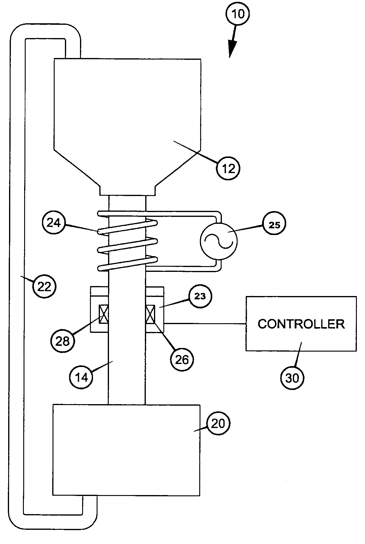
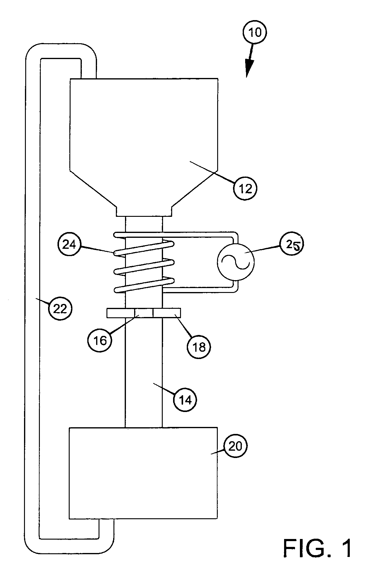
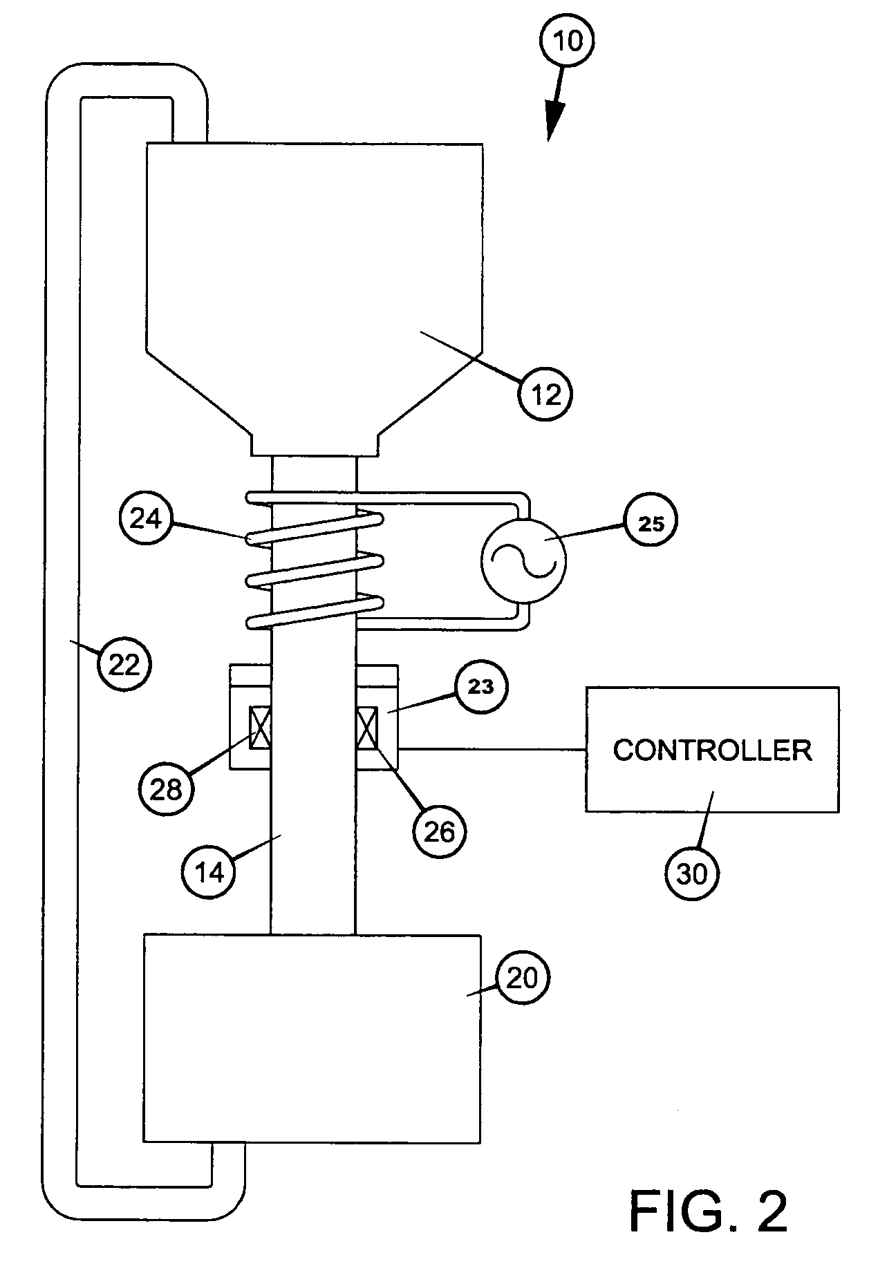
[0011]Referring now to FIG. 1, a typical shot peening or blast cleaning apparatus is generally indicated by the numeral 10. Media is stored in hopper 12 and then directed through a suitable flow path or conduit 14, which includes a regulating device, for example a fixed orifice 16 in an orifice plate 18. Typical size of the orifice 16 is, for example, 0.125″ or 0.250″. After the material passes through the orifice 16, the media enters treatment chamber 20, which includes, for example, a centrifugal throwing wheel (not shown) or a pneumatic blast nozzle (not shown), both of which are well known to those skilled in the art. The media impacts a target surface for its intended application and is then gathered in and resubmitted to the hopper 12 through return line 22.

[0012]As has been discussed above, it has been observed that impacts of the media with the target increase the tendency of the material to become “magnetized”. Additional impacts due to recirculation of the media tend to fu...


PUM

PropertyMeasurementUnit
Flow rateaaaaaaaaaa
Magnetic fieldaaaaaaaaaa
Currentaaaaaaaaaa

Abstract

The flow of media in shot peening, blast cleaning, and similar equipment is improved by applying a time varying magnetic field to the media to thereby degauss the media, allowing the media to flow through equipment without clogging and clumping due to magnetic attraction between the media.

Description

[0001]This application claims domestic priority based upon U.S. Provisional Patent Application Ser. No. 60 / 461,845, filed Apr. 10, 2003.TECHNICAL FIELD[0002]This invention relates to improving the flow of media in shot peening, blast cleaning, and similar equipment.BACKGROUND OF THE INVENTION[0003]Iron or steel granules, also called shot or grit, are used in abrasive blast cleaning, granite cutting, shot peening and other applications. The efficiency of such equipment depends upon media flowing freely through the apparatus and impacting upon the workpiece being treated. However, the flow characteristics of the media vary widely during operation of the equipment. Commonly, the media is directed against the workpiece and then collected and recycled through the equipment.SUMMARY OF THE INVENTION[0004]Such media materials are subject to magnetic remnance or memory which causes reduced flow capability because of the magnetic remnance or memory which causes reduced flow capability. This i...

Claims


Application Information

Patent Timeline
IPC IPC(8): B24B1/00B24C9/00B24C1/00B24C5/08B24C7/00B24C11/00
CPCB24C1/00B24C5/08B24C11/00B24C9/00B24C7/0069B32B1/02
Inventor CHAMPAIGNE, JACK
Owner ELEKTRONIK
Why Eureka
Try Eureka