
Heating apparatus using electromagnetic wave

a heating apparatus and electromagnetic wave technology, applied in electrical appliances, microwave heating, electric/magnetic/electromagnetic heating, etc., can solve the problems of significantly reducing the cut-off performance of electromagnetic waves, so as to increase the absorption bandwidth of electromagnetic waves, enhance the cut-off performance of harmonic frequencies generated by electromagnetic wave interference, and enhance the effect of electromagnetic wave performan

Active Publication Date: 2007-11-06
LG ELECTRONICS INC
View PDF7 Cites 0 Cited by
  • Summary
  • Abstract
  • Description
  • Claims
  • Application Information

AI Technical Summary

Benefits of technology

[0016]An object of the present invention is to provide a heating apparatus using an electromagnetic wave, by which a gap between a front side of a body and a choke filter can be minimized despite installation of a glass panel and gasket.
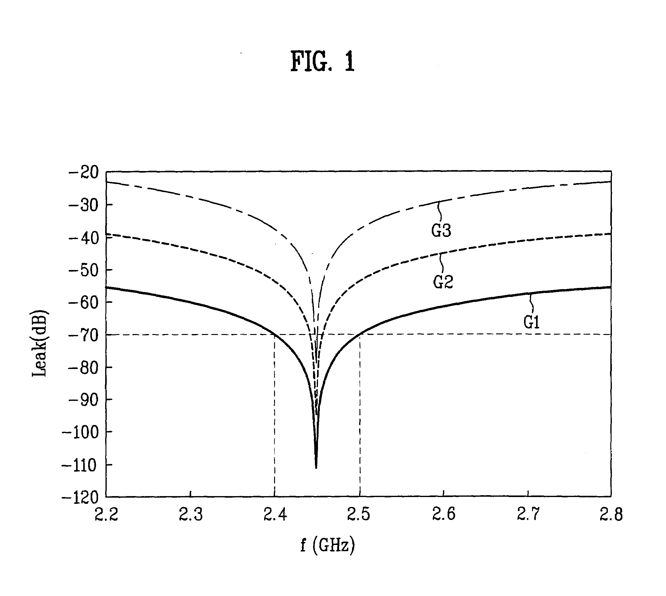
[0017]An object of the present invention is to provide a heating apparatus using an electromagnetic wave, by which cut-off performance of the electromagnetic wave is enhanced by increasing an electromagnetic wave absorption bandwidth having cut-off performance below −70 dB.
[0018]Another object of the present invention is to provide a heating apparatus using an electromagnetic wave, by which cut-off performance of a harmonic frequency generated from interference of the electromagnetic wave can be enhanced.
[0019]Another object of the present invention is to provide a heating apparatus using an electromagnetic wave, by which electromagnetic wave cut-off performance can be secured even if a front side thickness of a body is reduced.
[0020]A further object of the present invention is to provide a heating apparatus using an electromagnetic wave, by which sealing performance of a cavity and door cleaning facilitation are enhanced in a manner of reducing a gap between a front side of a body and a choke filter to increase an approximation effect.

Problems solved by technology

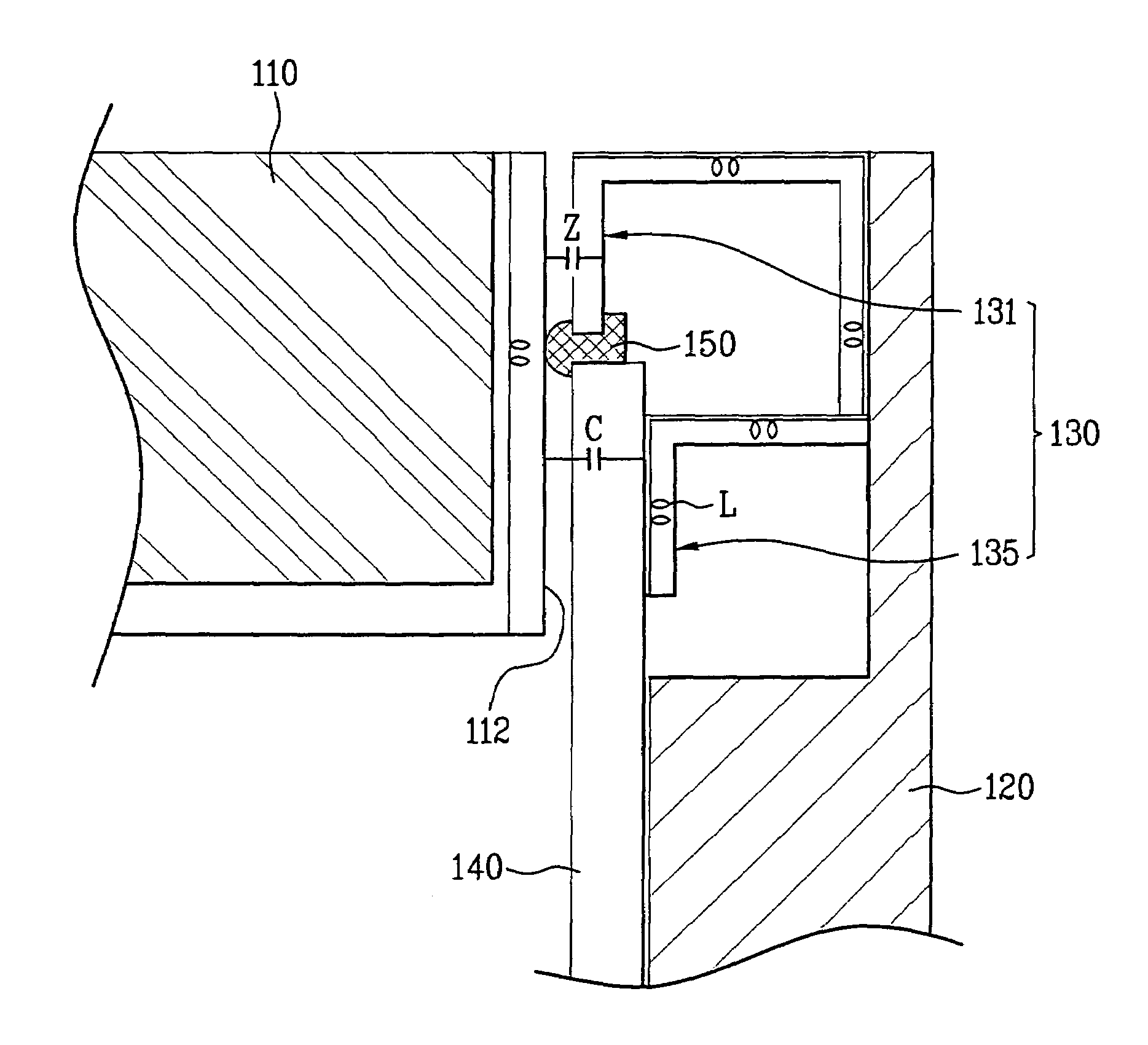
First of all, since the gasket and glass panel are installed at the door of the heating apparatus for the thermal insulation, a gap between the front side of the body and the choke filter is unable to avoid increasing. If the gap increases, capacitance (C) of the electromagnetic wave cut-off performance is reduced so that a graph, as shown in FIG. 1, has a sharp peak to considerably reduce an electromagnetic wave absorption bandwidth having the cut-off performance below about 70 dB. Hence, the electromagnetic wave cut-off performance is considerably lowered.
Yet, in case that the gasket and the glass panel are installed at the door of the heating apparatus, a substantial gap between the front side of the door and the choke filter is about 6˜7 mm, it can be seen that the electromagnetic wave cut-off performance is considerably reduced.
Secondly, the cavity has the EMI (electromagnetic interference) characteristic since the electromagnetic wave interference or electromagnetic interference (EMI) is generated by a harmonic frequency due to the interference of the frequency of 2.45 GHz.
As the electromagnetic wave bandwidth is reduced, it becomes difficult to eliminate the harmonic frequency.
Thus, limitation is put on reducing the wall thickness of the body.

Method used


Image

  • Heating apparatus using electromagnetic wave
  • Heating apparatus using electromagnetic wave
  • Heating apparatus using electromagnetic wave

Examples


Embodiment Construction

[0038]Reference will now be made in detail to the preferred embodiments of the present invention, examples of which are illustrated in the accompanying drawings. Wherever possible, the same reference numbers will be used throughout the drawings to refer to the same or like parts.

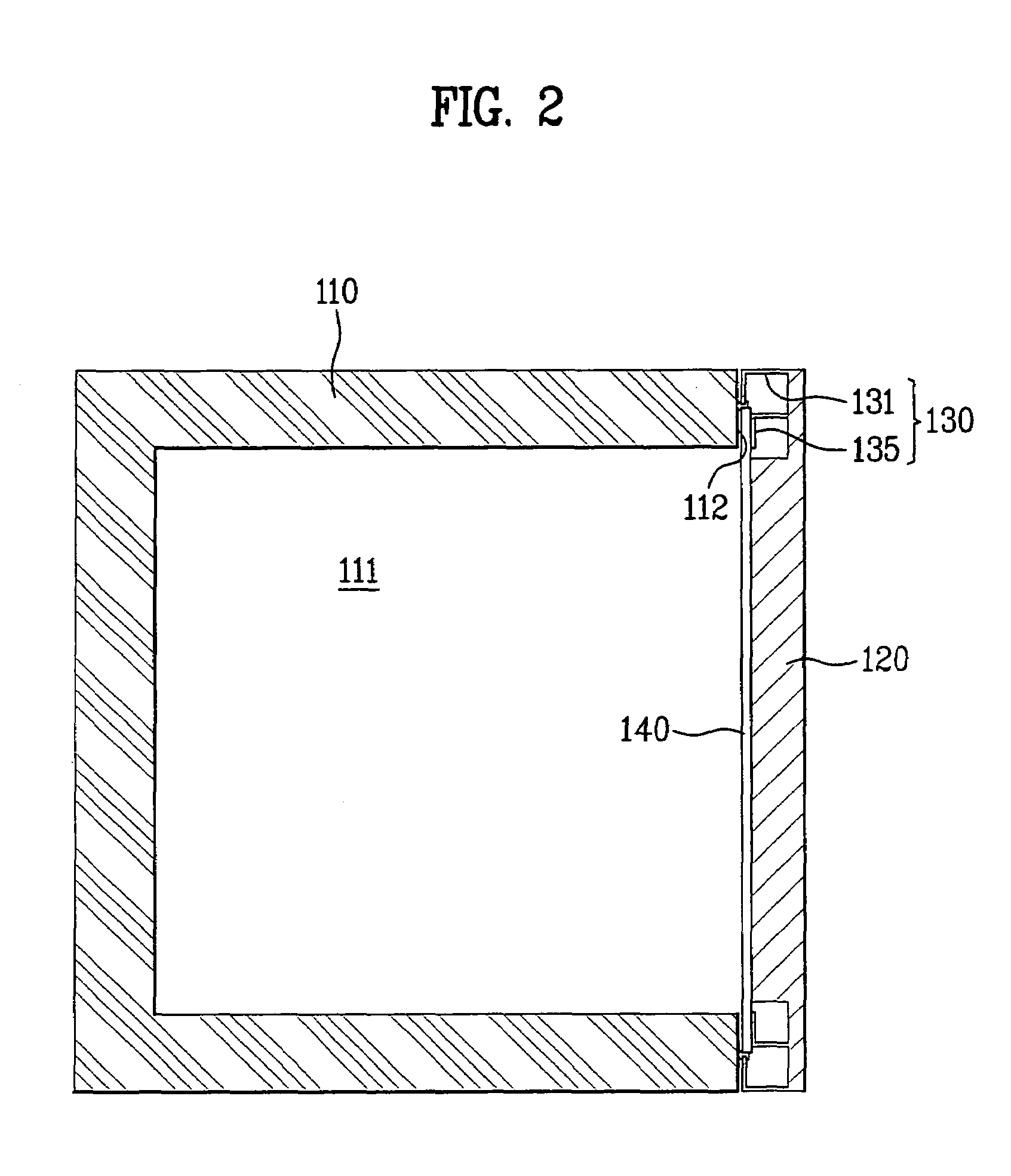
[0039]FIG. 2 is a cross-sectional diagram of a heating apparatus using an electromagnetic wave according to a first embodiment of the present invention, and FIG. 3 is a perspective diagram of a choke filter in FIG. 2.

[0040]Referring to FIG. 2 and FIG. 3, a heating apparatus using an electromagnetic wave according to a first embodiment of the present invention includes a door 120 provided to an open front side 112 of a body 110 to be opened / closed, a choke filter 130 having a panel type choke part 131 arranged by at least one or more rows along an edge of the door 120 and a filter part 135 having a plurality of slots 135b wherein a prescribed choke part 131 is provided to a most outer side, and a glass panel ...


PUM


Abstract

A heating apparatus using an electromagnetic wave is disclosed, by which a capacity of a cavity is increased and by which cut-off performance of the electromagnetic wave and facilitation of door cleaning can be enhanced. The present invention includes a door provided to an open front side of a body to be opened / closed, a choke filter having a panel type choke part arranged by at least one or more rows along an edge of the door and a filter part having a plurality of slots wherein a prescribed choke part is provided to a most outer side, and a glass panel attached to an inner lateral side of the door and the choke filter.

Description

[0001]This application claims the benefit of the Korean Patent Application No. P2005-0076739, filed on May 22, 2005, which is hereby incorporated by reference as if fully set forth herein.BACKGROUND OF THE INVENTION[0002]1. Field of the Invention[0003]The present invention relates to a heating apparatus, and more particularly, to a heating apparatus using an electromagnetic wave. Although the present invention is suitable for a wide scope of applications, it is particularly suitable for increasing a capacity of a cavity, enhancing cut-off performance of the electromagnetic wave, and enhancing facilitation of door cleaning.[0004]2. Discussion of the Related Art[0005]Generally, an electronic oven, a microwave oven and the like are devices for heating food and drink using an electromagnetic wave. And, a heating apparatus using an electromagnetic wave is the general term for theses devices.[0006]A heating apparatus using an electromagnetic wave according to a related art includes a chok...

Claims


Application Information

Patent Timeline
Patent Type & Authority Patents(United States)
IPC IPC(8): H05B6/76
CPCH05B6/763H05B6/76
Inventor KIM, EUNG SUHU, JIN YULSIM, SUNG HUN
Owner LG ELECTRONICS INC
Learn More