
Measuring formation density through casing

a technology of density measurement and casing, which is applied in the direction of seismology for waterlogging, using reradiation, instruments, etc., can solve the problems of insufficient account for the many types of differing conditions encountered, the technique has not become widely used, and the depth of investigation is relatively shallow

Active Publication Date: 2007-11-06
SCHLUMBERGER TECH CORP
View PDF15 Cites 29 Cited by
  • Summary
  • Abstract
  • Description
  • Claims
  • Application Information

AI Technical Summary

Benefits of technology

[0008]While specifically designed for open hole applications, Applicants have discovered that the addition of the short spacing detector between the backscatter detector and the long spacing detector allow

Problems solved by technology

While conventional open hole gamma ray density tools have occasionally been used to make formation density-related measurements in cased wells, this technique has not become widely used because the relatively weak gamma ray sources (typically a Cesium-137 source emitting gamma rays at 662 keV) and relatively short source / receiver spacings used in conventional open hole gamma ray density tools results in a relatively shallow depth of investigation, often insufficiently deep to make accurate formation density measurements through casing.
In addition, the use of conventional open hole gamma ray density measurement data processing methodologies have not sufficiently accounted for the many types of differing conditions encountered while making measurements through casing, such as variations in apparent casing thickness due to corrosion, casing collars, centralizers, etc.
Although the need for a gamma ray density behind casing measurement is not seriously in doubt, the tool proposed in these papers (or any other tool specifically designed to make gamma ray density measurements behind casing) has never been commercially successful.

Method used


Image

  • Measuring formation density through casing
  • Measuring formation density through casing
  • Measuring formation density through casing

Examples


Embodiment Construction

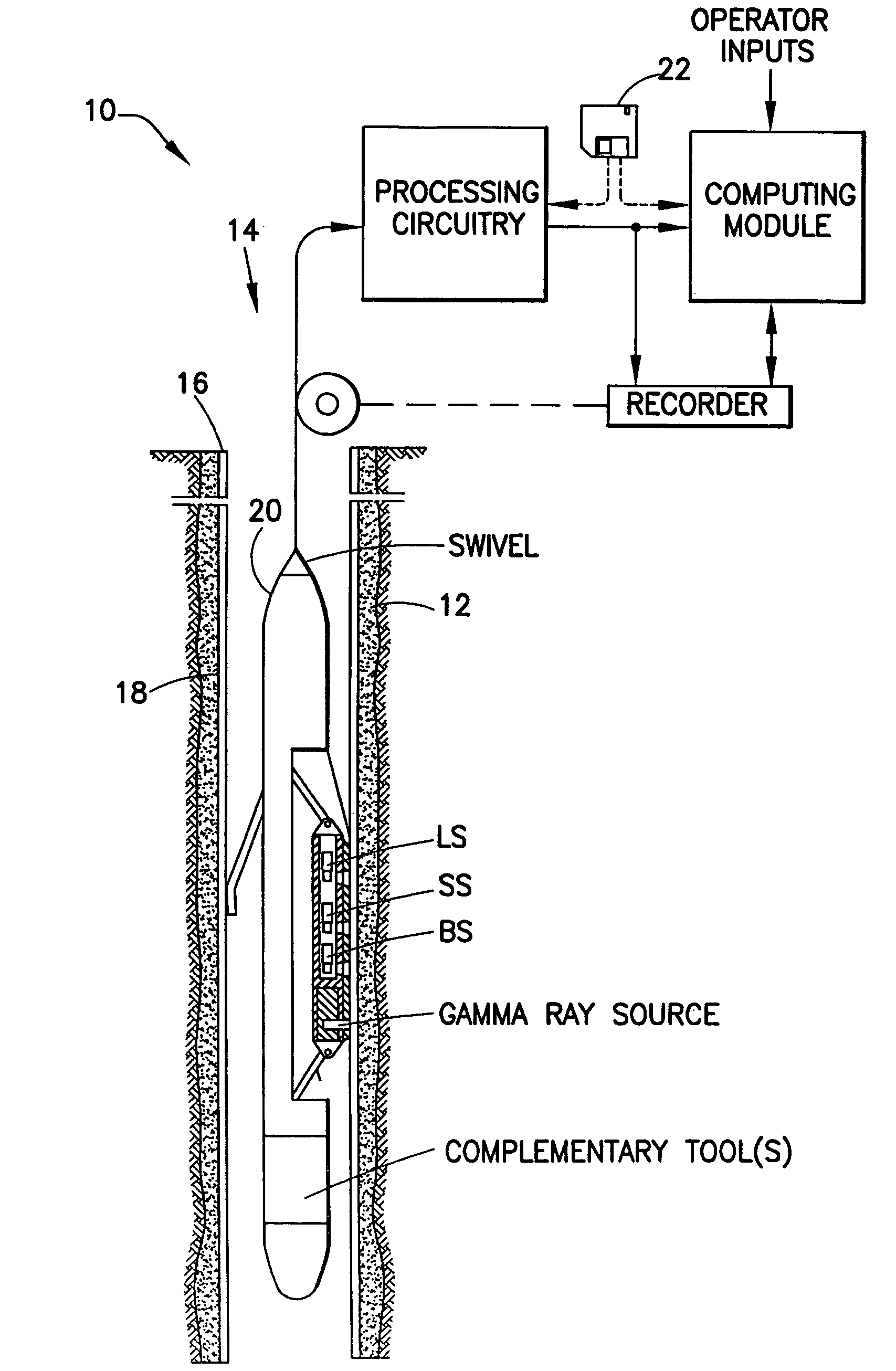
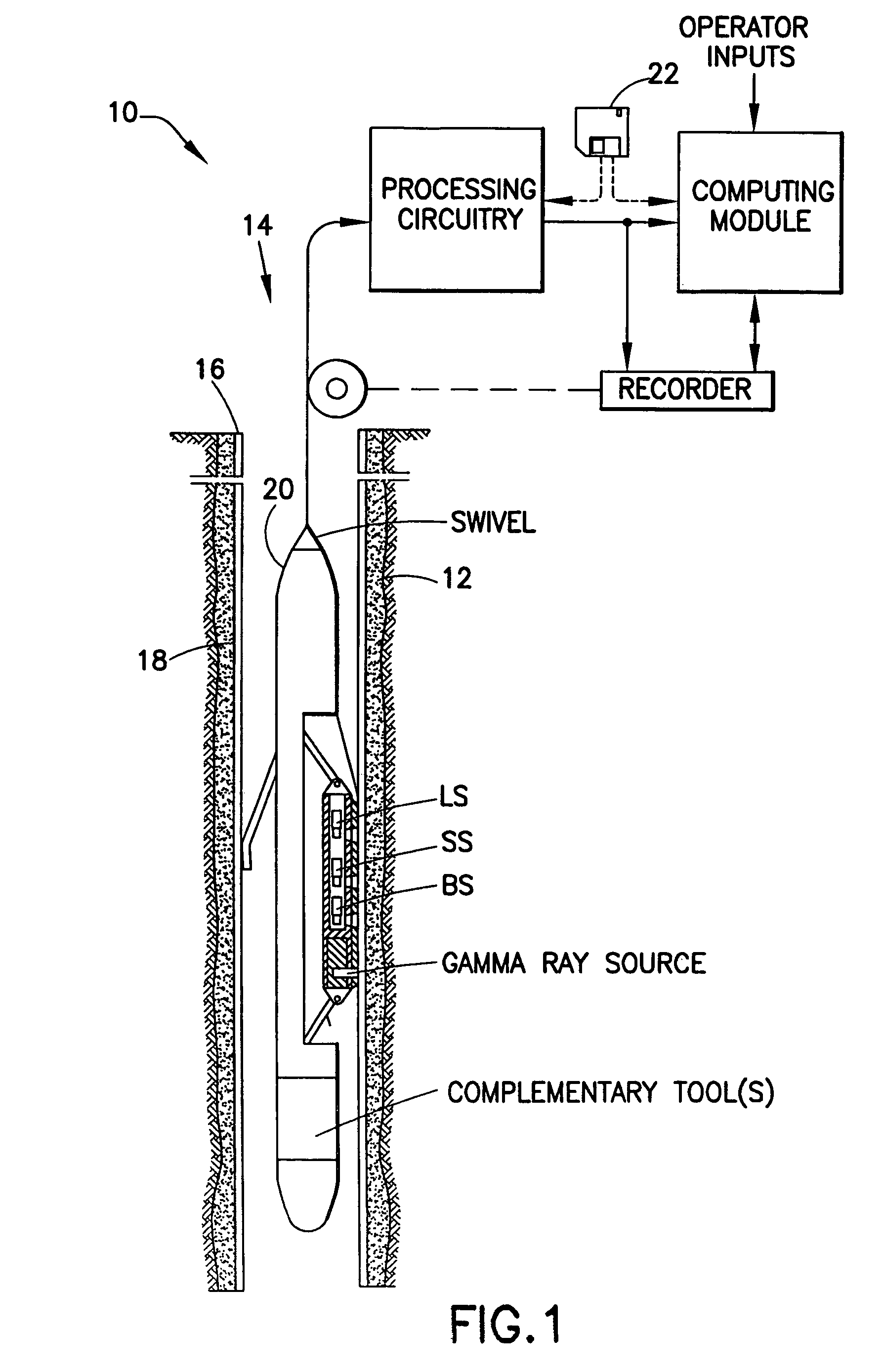
[0014]An example wireline data acquisition and processing system 10 is shown deployed within a subsurface formation 12. A borehole 14 has been drilled within the subsurface formation 12, casing 16 has been placed within the borehole, and cement 18 has been forced into the annulus between the borehole and the casing. Logging tools 20 are suspended in the borehole 14 on a cable, the deployed length of which substantially determines the depth of the logging tools within the subsurface formation 12. A swivel is provided to allow the logging tools 20 to rotate with respect to the cable, as discussed in more detail below. The cable length is controlled by conventional means at the surface (not shown). Conventional means are used to monitor the depth of tools 20 within the formation 12 and to process, compute, and record the measurements made by sensors within the tool. An article of manufacture, such as floppy disk 22, or another type of optical, magnetic, or electronic media may be used ...


PUM


Abstract

A method of determining formation density in a cased hole environment using a logging tool having a gamma ray source, a long spacing detector, and a short spacing detector that includes developing one or more cased hole calibration relationships that utilize differences between scattered gamma rays observed by short spacing detectors and scattered gamma rays observed by long spacing detectors to determine corrected formation density values, and using the cased hole calibration relationships and scattered gamma ray measurements obtained by the long spacing detector and the short spacing detector to determine the formation density. An associated article of manufacture and computerized well logging system are also described.

Description

RELATED APPLICATION[0001]This application claims the benefit of U.S. Provisional Application No. 60 / 442,364, filed Jan. 24, 2003.FIELD OF THE INVENTION[0002]The present invention relates to a method of determining the density of a subsurface formation and, more particularly, to a method of determining the density of a subsurface formation through casing.BACKGROUND OF THE INVENTION[0003]The use of gamma ray scattering measurements to measure the density of subsurface formations is well known. A general introduction to this topic can be found in Well Logging for Earth Scientists, by Darwin V. Ellis, Elsevier Science Publishing Co., Inc., 1987, pgs. 201-212, incorporated herein by reference. Gamma ray density measurement logging tools were initially developed for open hole applications and the earliest single detector tools were soon replaced by dual detector tools that allow compensations to be made for the possible intervening presence of mudcake or drilling fluid between the tool an...

Claims


Application Information

Patent Timeline
IPC IPC(8): G01V5/10G01V5/04G01V5/12
CPCG01V5/125
Inventor ELLIS, DARWIN V.MARKLEY, MARVIN E.
Owner SCHLUMBERGER TECH CORP
Learn More