Methods and systems for detecting memory address transfer errors in an address bus

a technology of memory address and transfer error, applied in error detection/correction, instruments, computing, etc., can solve the problems of poor electrical connection, electronic noise, and large address bus prone to transfer errors

Active Publication Date: 2007-11-06
ORACLE INT CORP
View PDF12 Cites 42 Cited by
  • Summary
  • Abstract
  • Description
  • Claims
  • Application Information

AI Technical Summary

Benefits of technology

[0008]In accordance with a first aspect of the present invention, a method for detecting transfer errors in an address bus is provided. In this method, a first address parity is generated using a memory address. Next, at least two error-correction-code (ECC) check bits are scrambled using the first address parity. Subsequently, the data ECC check bits are written to a memory and the data ECC check bits enable detection of transfer errors in the address bus.
[0009]In accordance with a second aspect of the present invention, a method for detecting transfer errors in an address bus is provided. In this method, a second address parity is generated using a memory address. Next, data ECC check bits are read from the memory. Subsequently, at least two previously scrambled data ECC check bits are unscrambled using the second address parity and the data ECC check bits enable detection of transfer errors in the address bus.
[0010]In accordance with a third aspect of the present invention, a system for detecting transfer errors in an address bus is provided. The system includes a first parity generator for generating a first address parity using a memory address. Additionally, at least two exclusive-OR operators coupled to the first parity generator for scrambling at least two data ECC check bits using the first address parity. The first parity generator and the at least two exclusive-OR operators coupled to the first parity generator enable detection of transfer errors in the address bus.

Problems solved by technology

Larger address buses are more prone to transfer errors because more memory addresses are transferred.
Transfer errors may result from electronic noise, faulty wires, electro-migration problems, and poor electrical connections, and the transfer errors cause data to be accessed from and written to incorrect memory addresses.
However, a memory module with additional pins cannot plug into existing memory sockets.
Adding parity protection to address buses 106 is thus not feasible with existing hardware systems.

Method used


Image

  • Methods and systems for detecting memory address transfer errors in an address bus
  • Methods and systems for detecting memory address transfer errors in an address bus
  • Methods and systems for detecting memory address transfer errors in an address bus

Examples


Embodiment Construction

[0021]An invention is disclosed for methods and systems for detecting transfer errors in an address bus. In the following description, numerous specific details are set forth in order to provide a thorough understanding of the present invention. It will be understood, however, by one of ordinary skill in the art, that the present invention may be practiced without some or all of these specific details. In other instances, well known process operations have not been described in detail in order not to unnecessarily obscure the present invention.

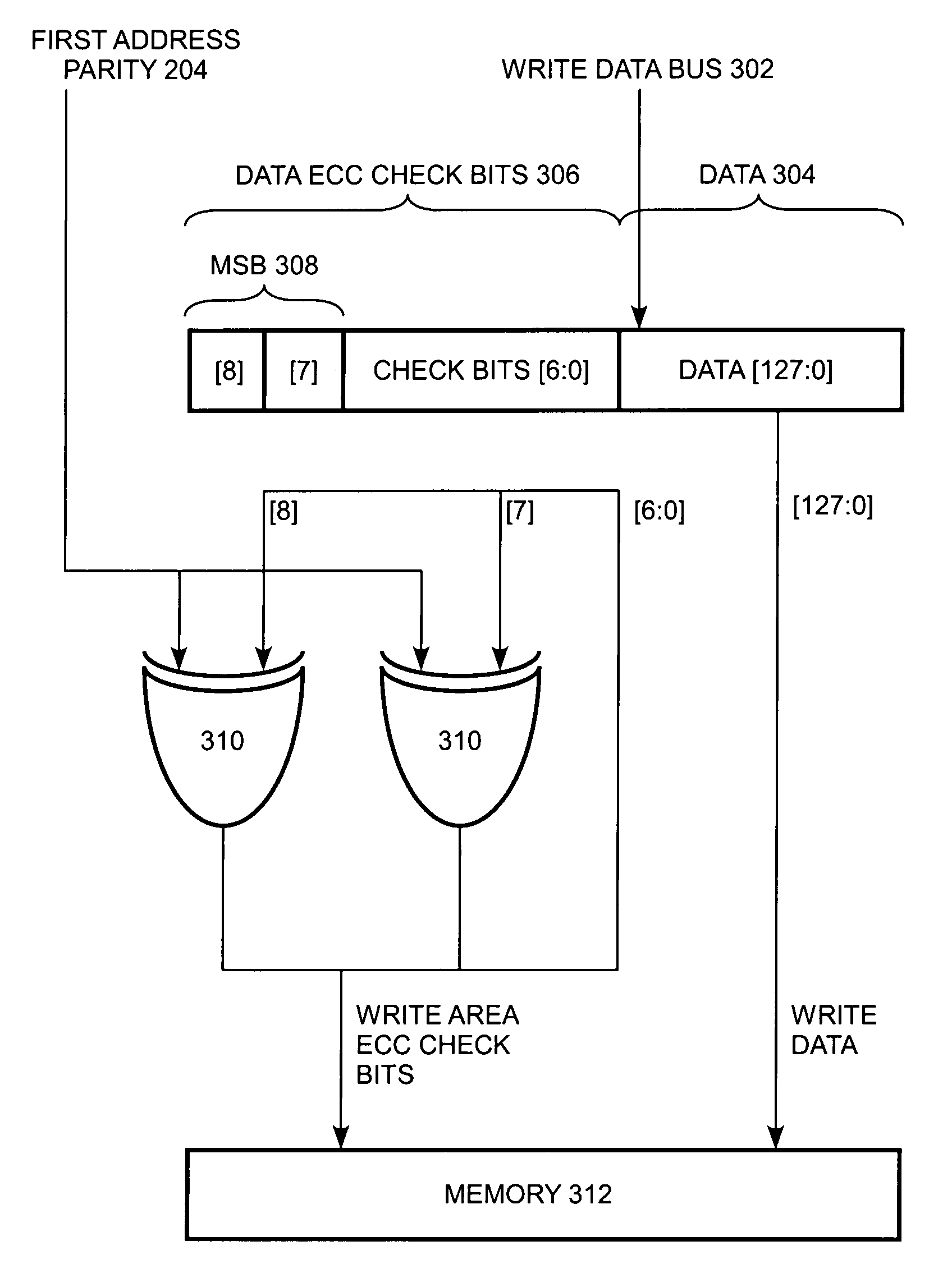
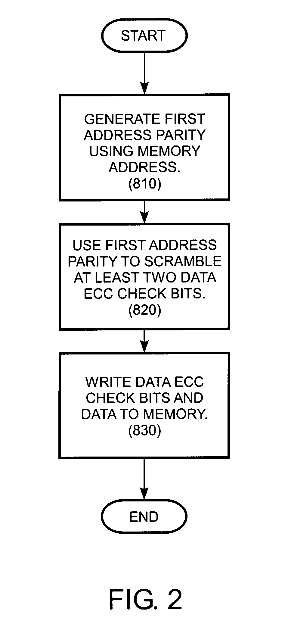
[0022]To detect transfer errors of a memory address in an address bus without adding new pins, the embodiments described herein provide methods and systems that utilize existing error correction code (ECC) for data that detects and corrects transfer errors in a data bus. Essentially, data ECC check bits used to detect transfer errors in the data bus are overloaded with an address parity. As will be explained in more detail below, the data ECC ...


PUM


Abstract

A method for detecting transfer errors in an address bus is provided. In this method, a first address parity is generated using a memory address. Next, at least two data error-correction-code (ECC) check bits are scrambled using the first address parity. Subsequently, the data ECC check bits are written to a memory and the data ECC check bits enable detection of transfer errors in the address bus. A system for detecting transfer errors in an address bus is also described.

Description

BACKGROUND OF THE INVENTION[0001]1. Field of the Invention[0002]The present invention relates to error detection and, more particularly, to methods and systems of detecting transfer errors in an address bus.[0003]2. Description of the Related Art[0004]Microprocessors include a hierarchy of memory subsystems. FIG. 1 is a simplified block diagram of a conventional microprocessor with memory subsystems. As shown in FIG. 1, central processing unit (CPU) core 100 is connected to memory subsystems by address buses 106 and data buses 108. The memory subsystems include level 2 on-chip cache 102 for storing data that require low access latency and larger off-chip main memories 104 for storing data that require high access bandwidths.[0005]Transfers of data from CPU core 100 to and from the memory subsystems through data buses 108 are typically protected by Error Correction Code (ECC). However, transfer of memory addresses through address buses 106 are not protected. Adding parity protection ...

Claims


Application Information

Patent Timeline
Patent Type & Authority Patents(United States)
IPC IPC(8): G11C29/00
CPCG06F11/1016G11C29/025G11C2029/0409
Inventor WONG, SAMSON S.ARAVINTHAN, KANDASAMYLEVINSKY, GIDEON N.DOR, SHAHARVAN, RICHARD T.LU, JIEJUN
Owner ORACLE INT CORP
Why Eureka
Try Eureka