
Multiple tape laying apparatus and method

a technology of multi-layer continuous fibers and laying apparatus, which is applied in the direction of mechanical control devices, instruments, paper/cardboard articles, etc., can solve the problems of limiting the throughput of the tape being applied, complicated equipment and control means, and the method and apparatus to automate the lamination of various structural shapes in said manner with multiple layers of continuous fibers preimpregnated with a resin binder remains unduly complex and expensive, and achieves the effect of satisfying the deposition of fiber

Active Publication Date: 2007-11-13
TRELLEBORG SEALING SOLUTIONS GERMANY
View PDF5 Cites 24 Cited by
  • Summary
  • Abstract
  • Description
  • Claims
  • Application Information

AI Technical Summary

Benefits of technology

The solution enables faster, more efficient, and cost-effective multi-directional tape laydown with reduced downtime and manufacturing costs, allowing for continuous operation and improved throughput by eliminating the need for head rotation and process interruptions.

Problems solved by technology

Such interruption of the tape laying procedure limits throughput of the tape being applied as well as complicates the equipment and control means being needed for unproductive apparatus movement.
The above disclosed method and apparatus to automatedly laminate various structural shapes in said manner with multiple layers of continuous fibers preimpregnated with a resin binder still remains unduly complex and expensive.
Tape laydown in said manner has been found to be relatively slow and require process interruption which understandably increases the cost of manufacture.
Moreover, the size and complexity of said apparatus for tape laydown causes excessive downtime to be experienced during continuous equipment operation.

Method used


Image

  • Multiple tape laying apparatus and method
  • Multiple tape laying apparatus and method
  • Multiple tape laying apparatus and method

Examples


Embodiment Construction

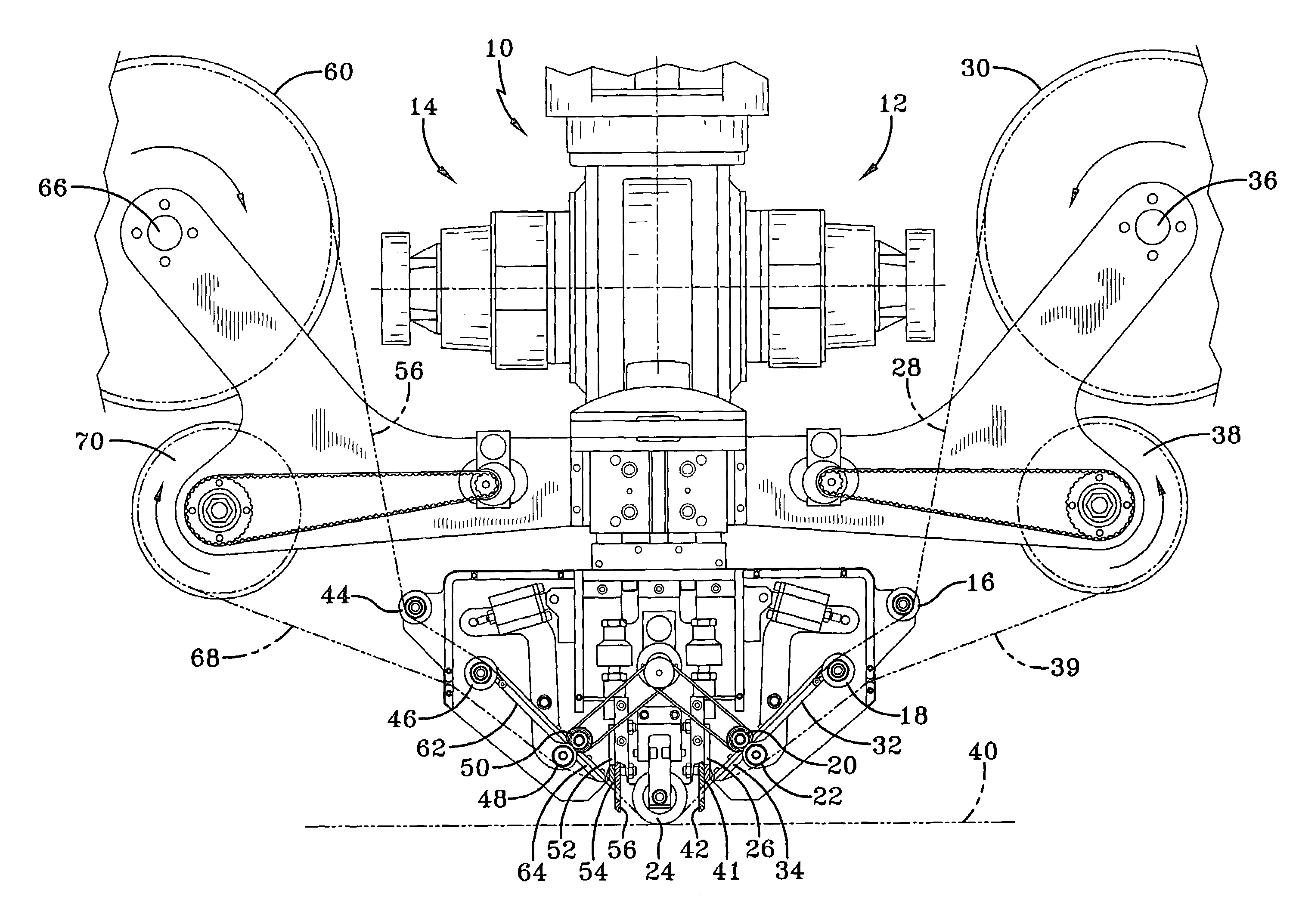
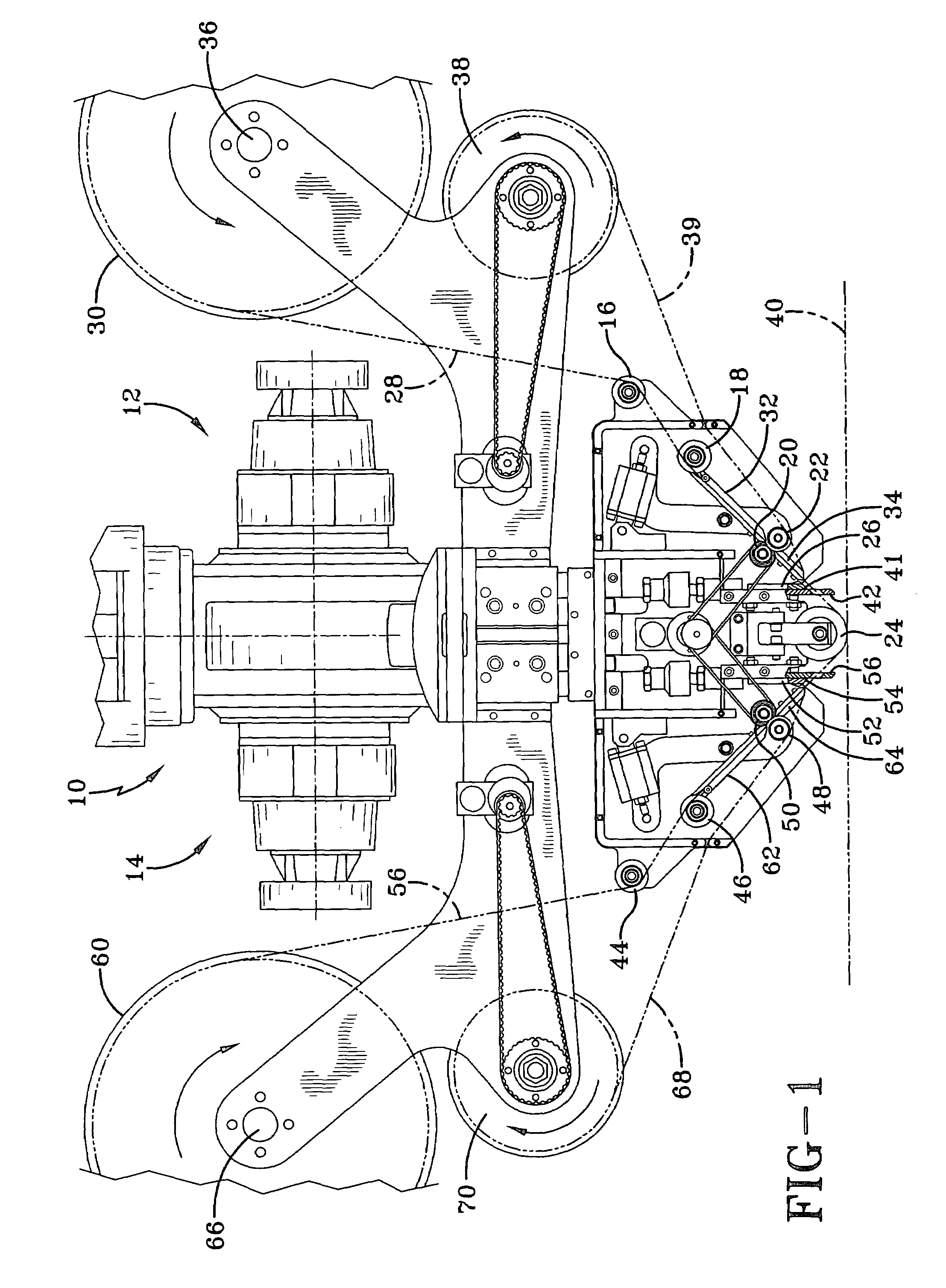
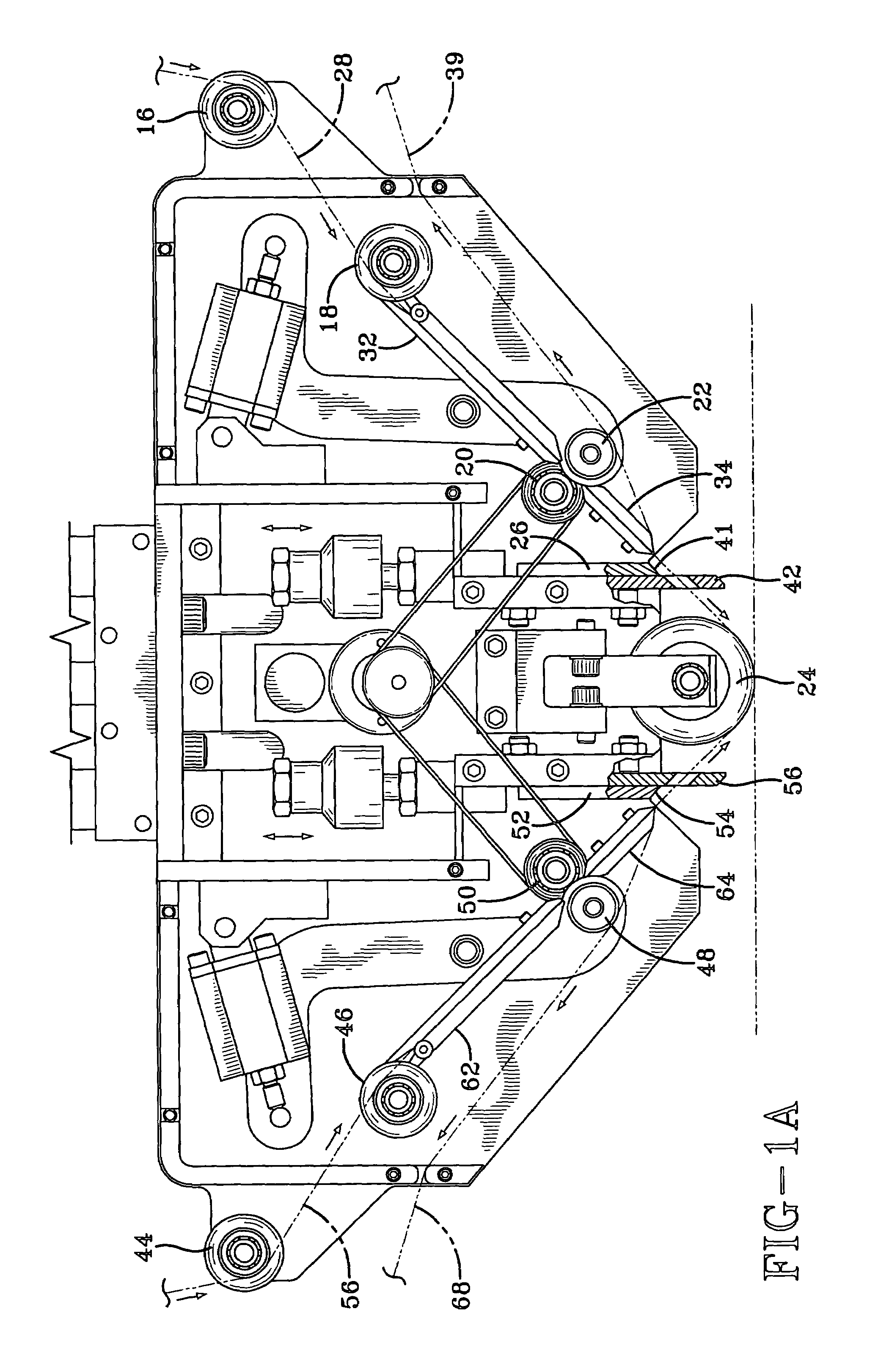
[0017]Referring to the drawings, there is shown in FIG. 1 a schematic side view for a tape laying apparatus according to the present invention. Basically, said movable tape laying member 10 houses duplicate spaced apart tape deposition means 12 and 14 which individually apply a predetermined length of the prepreg tape when said tape laying member is moving in different selected travel directions. To further illustrate said manner of tape deposition, the right side means of tape deposition 12 can deposit tape while the moving head member proceeds in one selected travel direction with the left side means of tape deposition 14 applying tape when the head member reverses its travel direction. Tape deposition means 12 includes a first pair of operationally cooperating guide or idler rollers 16 and 18, a second pair of operationally cooperating pinch rollers 20 and 22, a compaction roller 24 and a further included powered guillotine cutter mechanism 26. As can be observed, the resin impre...


PUM

PropertyMeasurementUnit
structural shapeaaaaaaaaaa
lengthaaaaaaaaaa
electrical controlaaaaaaaaaa

Abstract

A fully automated method and apparatus is disclosed to laminate various structural articles with multiple layers of a resin impregnated fiber tape. The fiber tape is deposited with a tape laying member moving alternately in different travel directions. The tape laying member removes all backing layers from the tape being employed, then deposits the unbacked tape on the surface of the structural article and finally severs the end of the tape being deposited. An automated cut and restart procedure is employed in the present apparatus to increase throughput.

Description

RELATED PROVISIONAL APPLICATION[0001]This application claims the benefit of U.S. Provisional Application Ser. No. 60 / 504,413 filed by the present applicant on Sep. 22, 2003.BACKGROUND OF THE INVENTION[0002]The present application relates generally to an improved method and apparatus for continuously applying multiple strips of continuous fiber tape to form various laminated structural articles and, more particularly, to doing so with a resin prepreg tape in a more simple and effective manner.[0003]In a co-pending application, issued as U.S. Pat. No. 7,063,118 to David E. Hauber, James P. Martin, Michael J. Pasanen, Robert J. Langone and Scott F. Miller which is also assigned to the present assignee, there is described a novel method and apparatus to reinforce various structural shapes with single strips of prepreg tape also being applied in a single direction. To reverse or change the tape laying direction with said apparatus generally requires rotation of the tape laying head or re...

Claims


Application Information

Patent Timeline
Patent Type & Authority Patents(United States)
IPC IPC(8): B29C65/52B32B37/16B32B38/10B65C9/18B65C9/30B32B37/20B65C9/12B29C70/38
CPCB29C70/388B29C70/545B44C1/165Y10T156/1057Y10T156/1707Y10T156/1365B29C2793/0027
Inventor MARTIN, JAMES P.
Owner TRELLEBORG SEALING SOLUTIONS GERMANY
Learn More