Multiple tape laying apparatus and method

a technology of multi-layer continuous fibers and laying apparatus, which is applied in the direction of paper hanging, mechanical control devices, instruments, etc., can solve the problems of limiting the throughput of the tape being applied, complicated equipment and control means, and the method and apparatus to automate the lamination of various structural shapes in said manner with multiple layers of continuous fibers preimpregnated with a resin binder remain unduly complex and expensive, and achieve the effect of satisfying the deposition of fiber prepr

Active Publication Date: 2005-03-24
TRELLEBORG SEALING SOLUTIONS GERMANY
View PDF5 Cites 241 Cited by
  • Summary
  • Abstract
  • Description
  • Claims
  • Application Information

AI Technical Summary

Benefits of technology

[0010] It has now been discovered by the present applicant that satisfactory deposition of the fiber prepreg can be carried out more effectively with a modified tape laying member providing multi-directional tape laydown in a particular manner. More specifically, the present apparatus employs a novel laterally moving tape laying head member having multiple spaced apart tape depositing means which are individually operated during the selected travel direction of said moving head member. Having the multiple tape deposition means in the present head member spaced apart in an opposing spatial relationship allows reversing direction by said head member without head rotation. The continuous fiber tape being alternately applied in such manner can be deposited on the structural shape with single compaction roller means after backing removal. Each of the multiple tape deposition means in the present head member includes a pair of operationally cooperating mechanisms to first remove the backing layer from the reinforcement tape and thereafter sever a predetermined length of the unbacked tape from the tape supply while still being continuously fed. Removal of the backing layer in the present head member further includes accumulation of the removed backing layer while each of the tape severing mechanisms in the multiple tape deposition means of the present head member include mechanical cutter means which cooperate with pinch roller means enabling forward tape movement when being fed while preventing backward tape movement during tape severance with said cutter means. The herein defined method of operating the present apparatus understandably permits controlled movement of the movable tape laying member in various directions achieved with programmed software instruction. It follows therefrom that already known program controllers or software programmed computers can direct all lateral and vertical movement required of the tape laying member in the present apparatus.
[0011] The present tape laying head member can still further include multiple tape supply and associated backing removal mechanisms for each of the multiple tape deposition means incorporated therein. In so doing, multiple strips of the reinforcement tape can be concurrently applied while the moving head member conducts a single traverse. The prepreg tape selected for such purpose can further include backing layers disposed on both major surfaces to better enable release of the tape from tape supply spools as well as to help avoid adhesion of the unbacked tape to surfaces physically contacted in the head member. When concurrently applying multiple tape strips with this type tape, however, each tape supply spool is desirably associated with a pair of rewind spools for accumulation of both backing layers being removed. The concurrent tape strip deposition is desirably further carried out in the present apparatus with all tape strips being transported to a single compaction roller provided in the head member which exerts a compressive force on the deposited strips. Suitable continuous fiber tape for deposition in the present apparatus include both thermoset and thermoplastic prepregs having a releasable storage layer, such as paper, plastic and the like. Prepregs of this type are already well known and commercially available including thermoset type prepregs having an uncured resin matrix for later curing by also well known customary procedures. Movement and position commands given automatedly to the tape laying head member in the present apparatus determines the tape laydown pattern. Accordingly, said automated control of the present apparatus can enable repetitive tape deposition from the same start position as well as depositing tape from different locations. Movement of the tape laying head during tape laydown can also be controlled with programmed instruction in still other respects. For example, such controlled movement of the head member along the length of already deposited tape enables the included compaction roller means to exert any desired additional compressive action. Similarly, the operational speed at which said included compaction roller means is controlled can be maintained in the present apparatus no greater than the laydown speed of the tape deposition.

Problems solved by technology

Such interruption of the tape laying procedure limits throughput of the tape being applied as well as complicates the equipment and control means being needed for unproductive apparatus movement.
The above disclosed method and apparatus to automatedly laminate various structural shapes in said manner with multiple layers of continuous fibers preimpregnated with a resin binder still remains unduly complex and expensive.
Tape laydown in said manner has been found to be relatively slow and require process interruption which understandably increases the cost of manufacture.
Moreover, the size and complexity of said apparatus for tape laydown causes excessive downtime to be experienced during continuous equipment operation.

Method used


Image

  • Multiple tape laying apparatus and method
  • Multiple tape laying apparatus and method
  • Multiple tape laying apparatus and method

Examples


Embodiment Construction

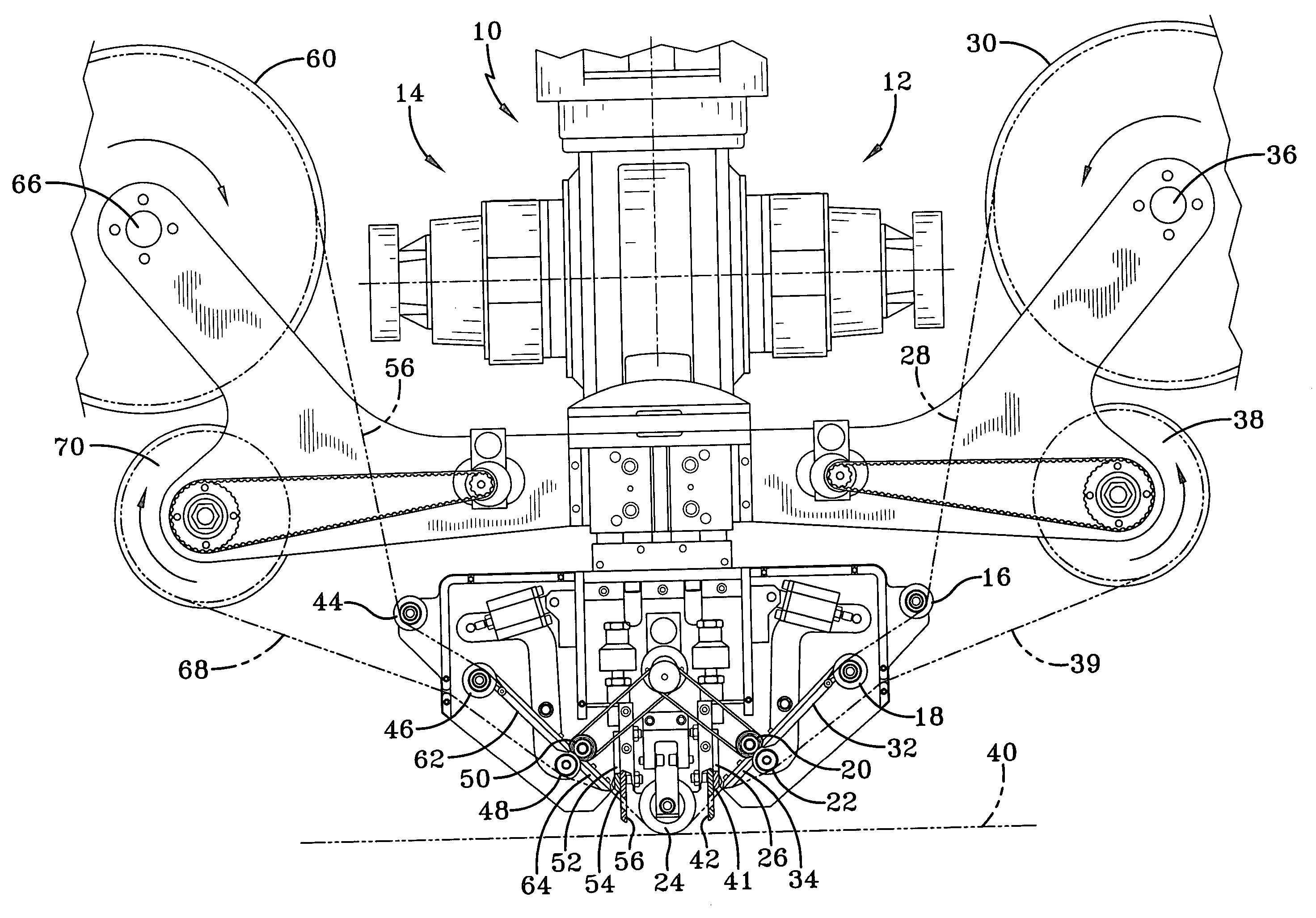
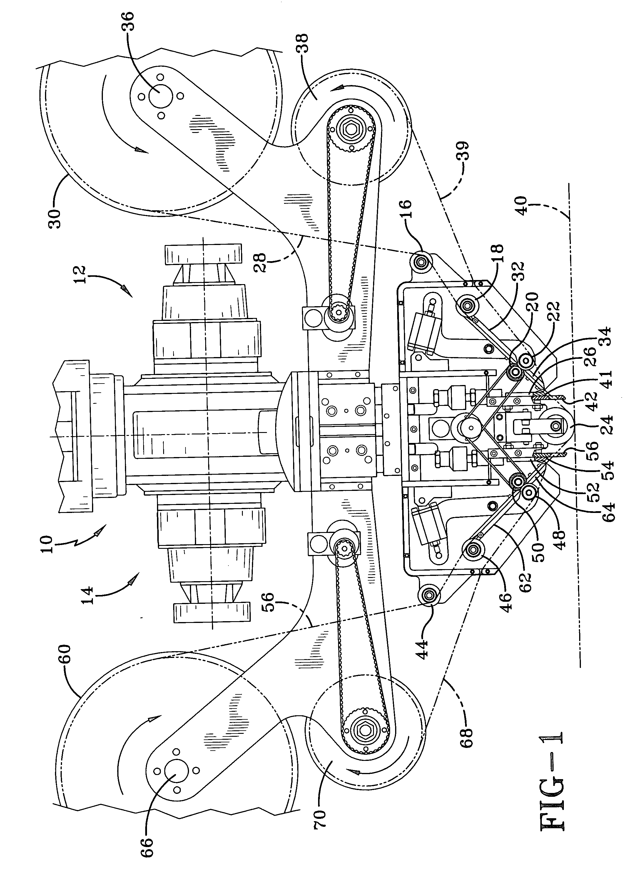
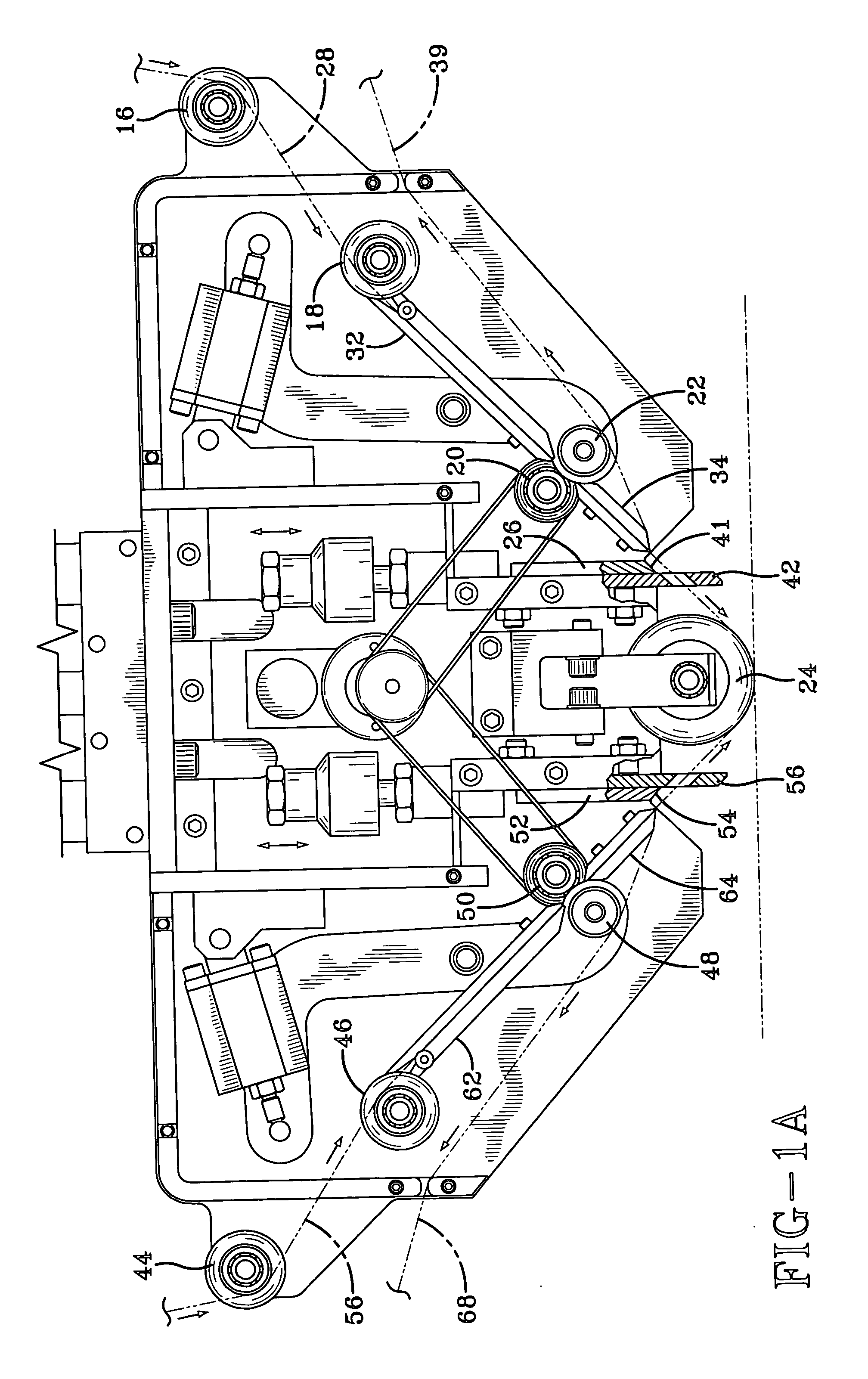
[0017] Referring to the drawings, there is shown in FIG. 1 a schematic side view for a tape laying apparatus according to the present invention. Basically, said movable tape laying member 10 houses duplicate spaced apart tape deposition means 12 and 14 which individually apply a predetermined length of the prepreg tape when said tape laying member is moving in different selected travel directions. To further illustrate said manner of tape deposition, the right side means of tape deposition 12 can deposit tape while the moving head member proceeds in one selected travel direction with the left side means of tape deposition 14 applying tape when the head member reverses its travel direction. Tape deposition means 12 includes a first pair of operationally cooperating guide or idler rollers 16 and 18, a second pair of operationally cooperating pinch rollers 20 and 22, a compaction roller 24 and a further included powered guillotine cutter mechanism 26. As can be observed, the resin impr...


PUM

PropertyMeasurementUnit
structural shapeaaaaaaaaaa
lengthaaaaaaaaaa
electrical controlaaaaaaaaaa

Abstract

A fully automated method and apparatus is disclosed to laminate various structural articles with multiple layers of a resin impregnated fiber tape. The fiber tape is deposited with a tape laying member moving alternately in different travel directions. The tape laying member removes all backing layers from the tape being employed, then deposits the unbacked tape on the surface of the structural article and finally severs the end of the tape being deposited. An automated cut and restart procedure is employed in the present apparatus to increase throughput.

Description

RELATED PROVISIONAL APPLICATION [0001] This application is related to Provisional Application Ser. No. 60 / 504,413 filed by the present applicant on Sep. 22, 2003.BACKGROUND OF THE INVENTION [0002] The present application relates generally to an improved method and apparatus for continuously applying multiple strips of continuous fiber tape to form various laminated structural articles and, more particularly, to doing so with a resin prepreg tape in a more simple and effective manner. [0003] In a co-pending application Ser. No. 10 / 717,022 filed Nov. 20, 2003 in the names of David E. Hauber, James P. Martin, Michael J. Pasanen, Robert J. Langone and Scott F. Miller which is also assigned to the present assignee, there is described a novel method and apparatus to reinforce various structural shapes with single strips of prepreg tape also being applied in a single direction. To reverse or change the tape laying direction with said apparatus generally requires rotation of the tape laying...

Claims


Application Information

Patent Timeline
Patent Type & Authority Applications(United States)
IPC IPC(8): B29C70/38
CPCB29C70/388B29C70/545Y10T156/1057Y10T156/1707Y10T156/1365B44C1/165B29C2793/0027
Inventor MARTIN, JAMES P.
Owner TRELLEBORG SEALING SOLUTIONS GERMANY
Why Eureka
Try Eureka