
Remote-control toy and field for the same

a remote control and toy technology, applied in the field of toy remote control, can solve the problems of users getting bored with the game, limited game procedures, and easy monotony of the game, and achieve the effect of improving the play experience and improving the playability

Active Publication Date: 2007-11-13
KONAMI DIGITAL ENTERTAINMENT CO LTD
View PDF6 Cites 1 Cited by
  • Summary
  • Abstract
  • Description
  • Claims
  • Application Information

AI Technical Summary

Benefits of technology

The present invention provides a remote-control toy with a wider variety of play content and more excitement through a means to affect the movable bodies in addition to the interactions of the movable bodies. The toy includes a controller that transmits a control signal, a movable body that is controlled to drive based on the control signal, and a field in which the movable body can move. The movable body includes a detecting unit that reacts to a predetermined object to be detected and outputs a detection signal, and a processing unit that performs predetermined processing in response to the output of the detection signal. The object to be detected can be embedded in the field and can change positions. The field can be joined to another field or the terrain of a user to create a more intricate and realistic environment. The technical effects of this invention include increased variety of play content, improved user experience, and more realistic and intricate environments.

Problems solved by technology

Therefore, the play contents such as the way of playing, the game procedures and so on are limited.
Because of this, the game is likely to become monotonous, and users get bored with it soon.
Also, to enjoy the thrill of attacks to be made on a movable body, it is always necessary for the user to have an opponent, because such a thrill cannot be felt when there is only one player.

Method used


Image

  • Remote-control toy and field for the same
  • Remote-control toy and field for the same
  • Remote-control toy and field for the same

Examples


Embodiment Construction

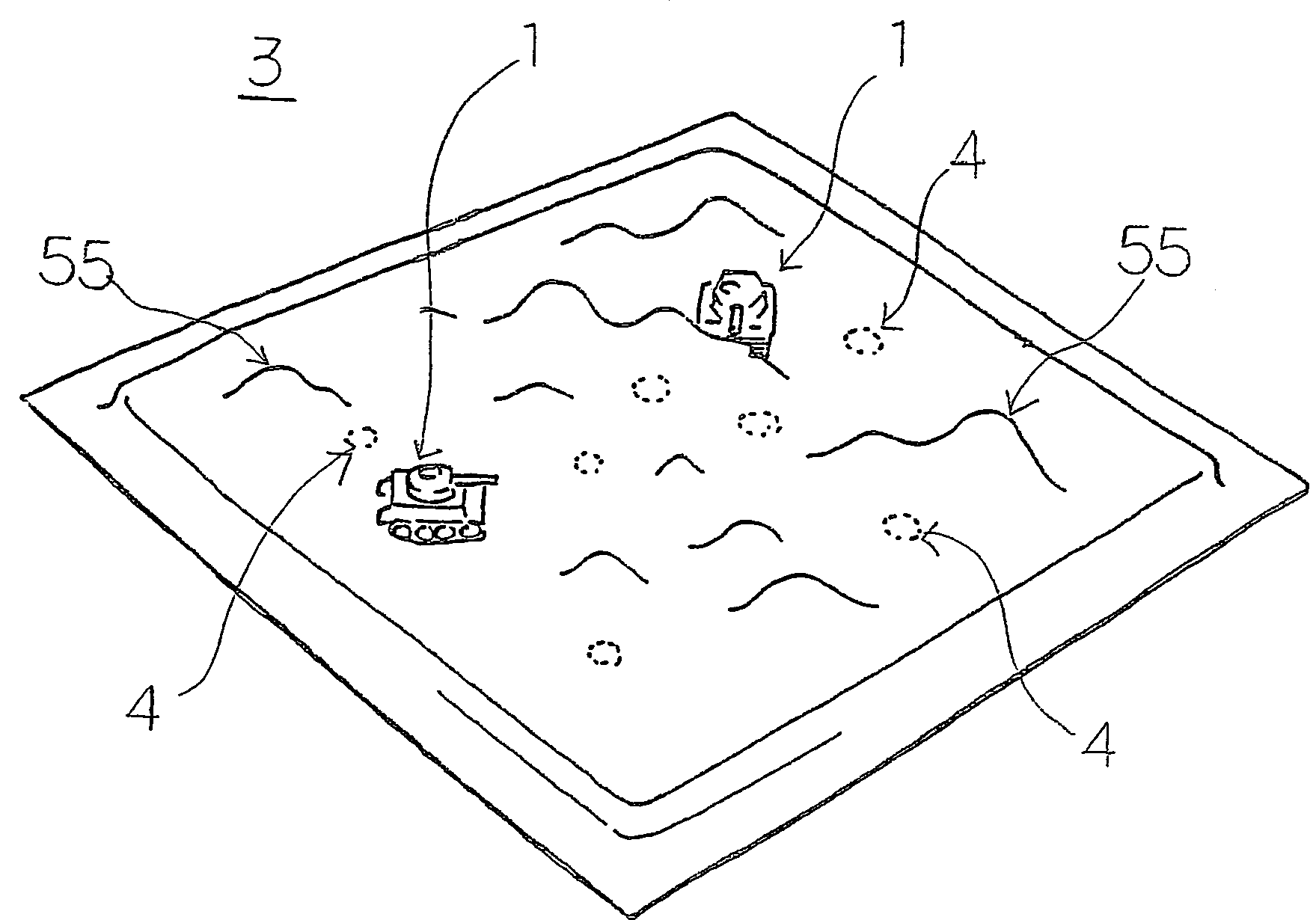
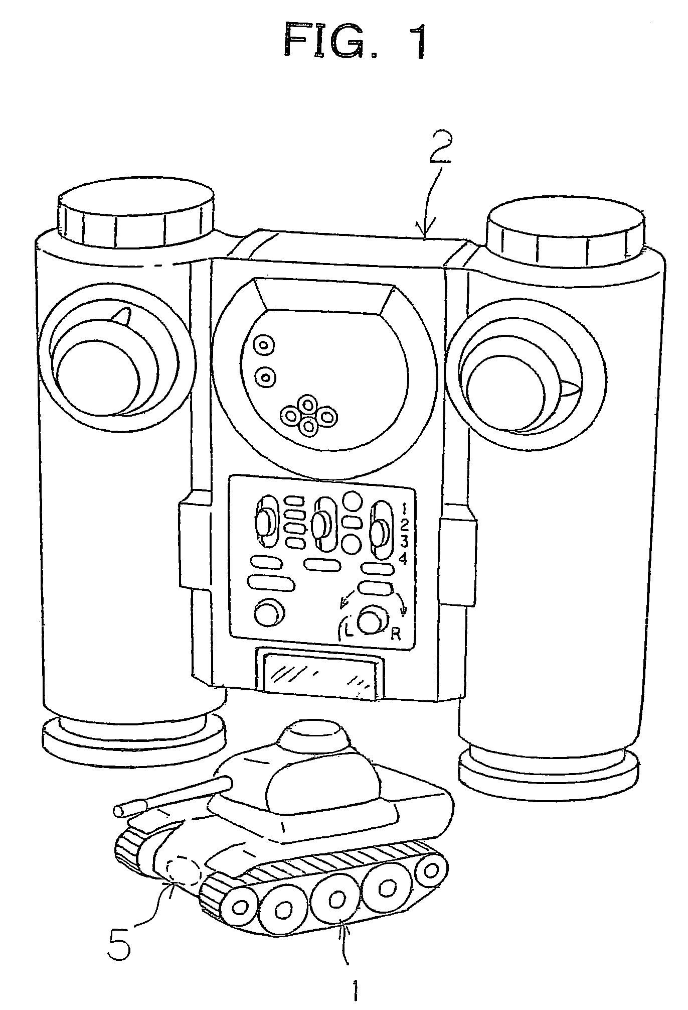
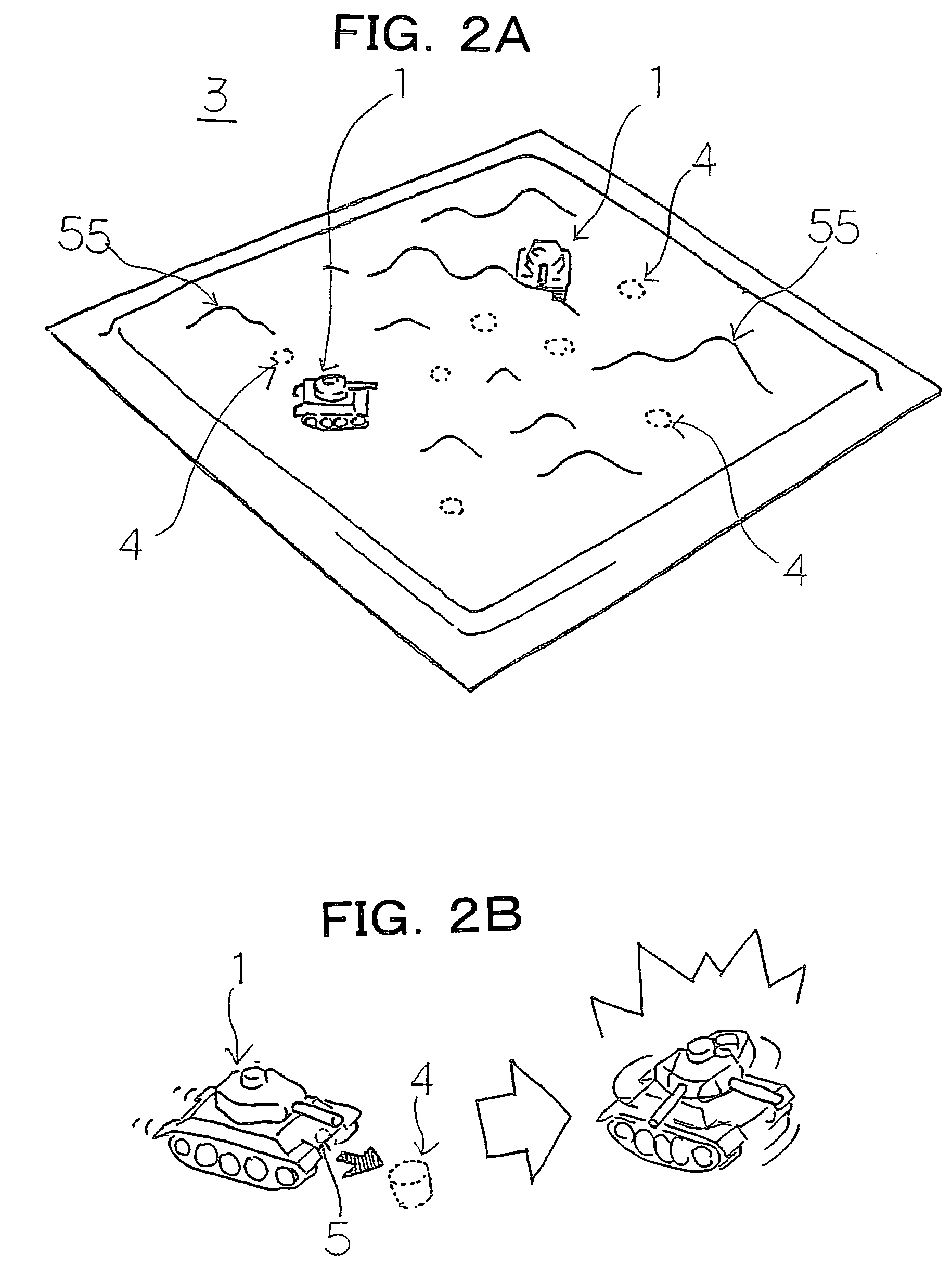
[0034]FIGS. 1 and 2A show an embodiment of the present invention. A combat vehicle model 1 as a movable body is remotely controlled with drive information contained in a control signal transmitted from a controller 2. The combat vehicle model 1 can move in a field 3. The means of any kind for remote-controlling the combat vehicle model 1 may be employed. For example, infrared rays, electric waves, or radio frequency may be employed. In this embodiment, two or more combat vehicles 1 can be remotely controlled at once, and can attack one another in a game. The field 3 has undulations 55 and magnets 4 as predetermined objects to be detected. Each combat vehicle model 1 has a magnetic line sensor 5 as the means of detecting the magnets 4. As shown in FIG. 1, the magnetic line sensor 5 is preferably located at a lower portion of the combat vehicle model 1, so as to facilitate the detection of the magnets 4. The structure of the field 3 and the method of placing the magnets 4 will be desc...


PUM


Abstract

A remote-control toy is provided that includes: a controller (2) that transmits a control signal according to an operation by a user; a movable body that is controlled to drive based on the control signal from the controller; and a field in which the movable body can move. The movable body includes a detecting unit that reacts to a predetermined object to be detected and outputs a detection signal, and a processing unit that performs predetermined processing in response to the output of the detection signal. The object to be detected can be placed in the field in such a manner that the position of the object to be detected can be changed.

Description

CROSS-REFERENCE TO PRIOR APPLICATION[0001]This is a U.S. national phase application under 35 U.S.C. §371 of International Patent Application No. PCT / JP2004 / 000279 filed Jan. 16, 2004, and claims the benefit of Japanese Patent Application No. 2003-010463 filed Jan. 17, 2003 which is incorporated by reference herein. The International Application published in Japanese on Aug. 5, 2004 as WO 2004 / 064958 A1 under PCT Article 21(2).TECHNICAL FIELD[0002]The present invention relates to a remote-control toy that transmits a control signal from a controller to a movable body, thereby controlling the movable body.BACKGROUND ART[0003]There have been games in which movable bodies such as combat vehicles of remote-control toys battle against each other in firing gun, for example.[0004]In such conventional battle games, however, the outcome of each game is decided only by interactions between the movable bodies (such as the magnitude of damage caused by each attack). Therefore, the play contents ...

Claims


Application Information

Patent Timeline
Patent Type & Authority Patents(United States)
IPC IPC(8): A63H30/04A63F9/14A63F3/00A63F9/00A63F9/34A63H17/045A63H17/39A63H18/10
CPCA63H30/04A63F3/00075A63F9/34A63F9/143A63H18/10
Inventor HAYASHI, RYOJI
Owner KONAMI DIGITAL ENTERTAINMENT CO LTD
Learn More