Manifold gasket accommodating differential movement of fuel cell stack

a technology of differential movement and fuel cell stack, which is applied in the field of fuel cell systems, can solve the problems of fuel cell stack shrinkage over its life, deterioration of gaskets, and wear during stack operation, and achieve the effects of promoting slippage, preventing deterioration of gaskets, and promoting slippage in these slip planes

a technology of differential movement and fuel cell stack, which is applied in the field of fuel cell systems, can solve the problems of fuel cell stack shrinkage over its life, deterioration of gaskets, and wear during stack operation, and achieve the effects of promoting slippage, preventing deterioration of gaskets, and promoting slippage in these slip planes

US7294427B2Active Publication Date: 2007-11-13FUELCELL ENERGY INC

Image

  • Manifold gasket accommodating differential movement of fuel cell stack
  • Manifold gasket accommodating differential movement of fuel cell stack
  • Manifold gasket accommodating differential movement of fuel cell stack

Examples


Embodiment Construction

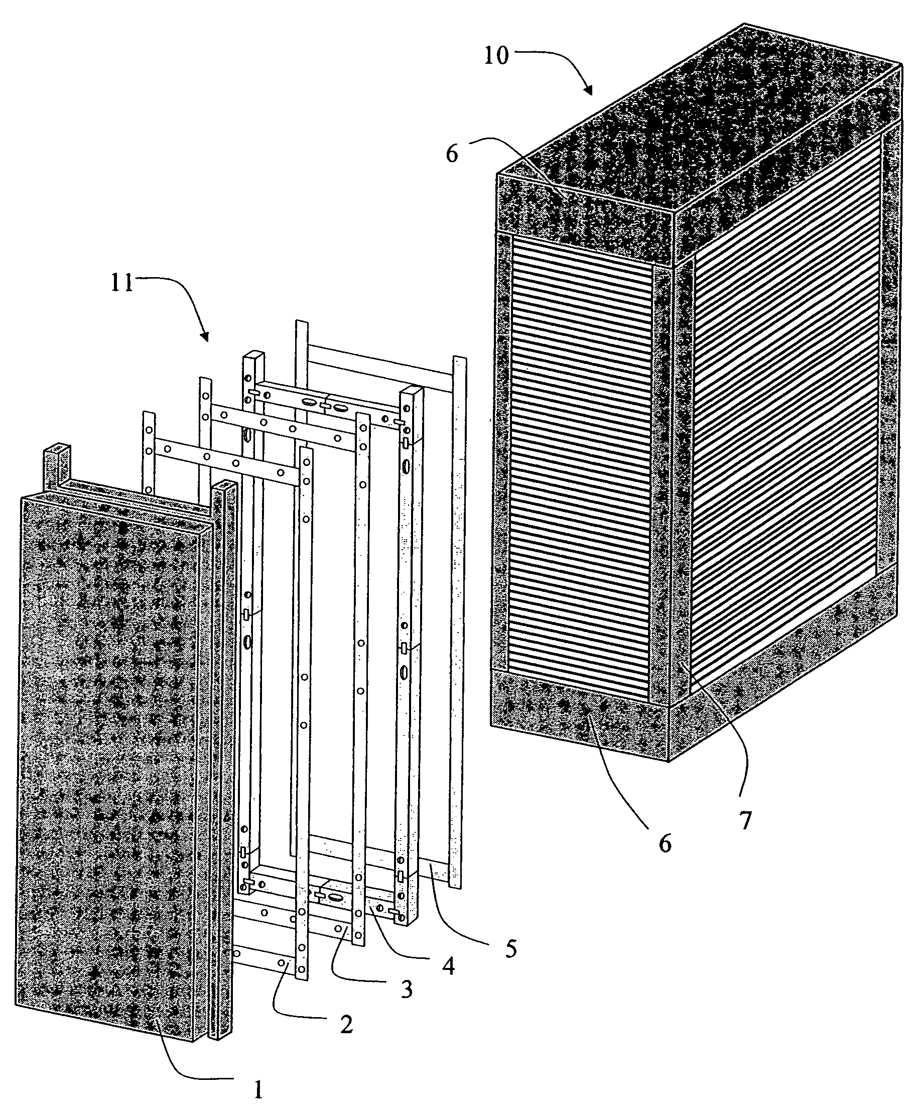
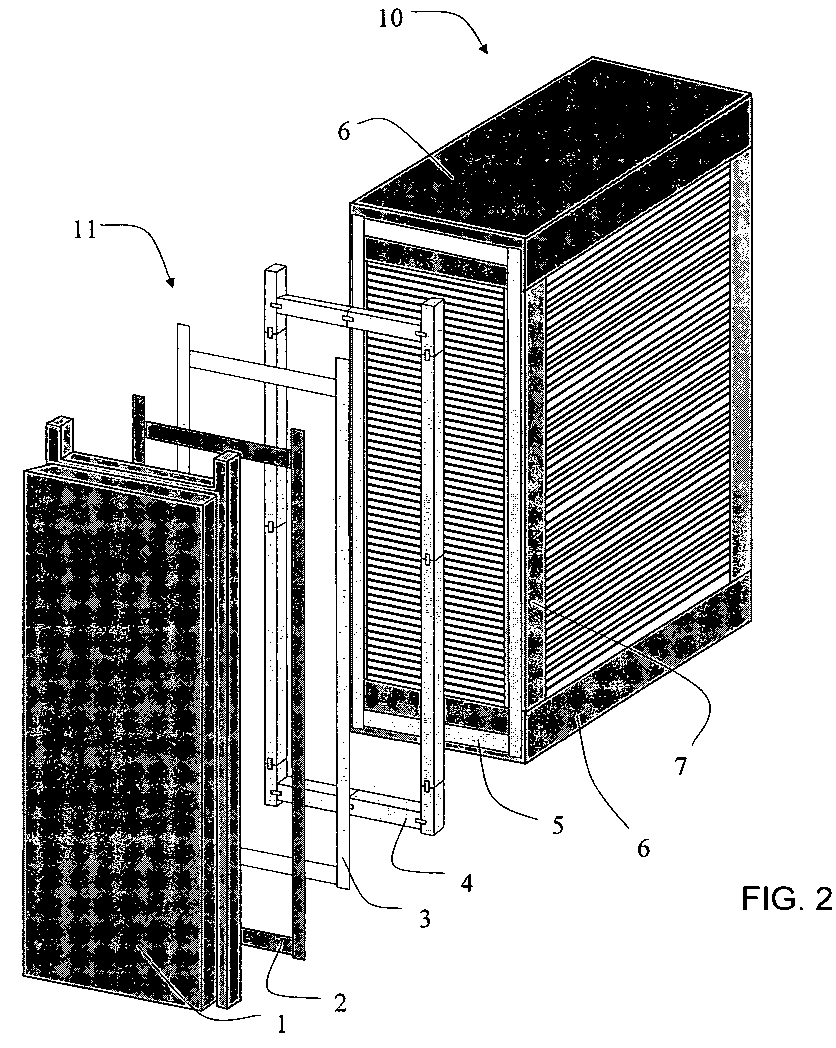
[0029]The present invention provides a gasket or seal that accommodates the changes in shape and dimension of a fuel cell stack that occur during stack life and the differential movements that result from such physical changes. These movements may be categorized as thermal movements, which occur during heating or cooling or result from operational variations, and internal cell compaction movements, which occur during the initial conditioning and longer-term creep of the components. The gasket described in detail below allows both types of movements and thus minimizes stresses imparted on the dielectric insulators.

[0030]In particular, the gasket limits stresses caused by the differences in coefficients of expansion between the manifold assembly and stack components. The materials described were evaluated and selected from tests that simulate relative movements between adjacent surfaces in contact at fuel cell operating conditions. A major consideration in the development of the gaske...


PUM

PropertyMeasurementUnit
dielectricaaaaaaaaaa
dielectric insulatoraaaaaaaaaa
lengthaaaaaaaaaa

Abstract

A gasket for use in a fuel cell system having at least one externally manifolded fuel cell stack, for sealing the manifold edge and the stack face. In accordance with the present invention, the gasket accommodates differential movement between the stack and manifold by promoting slippage at interfaces between the gasket and the dielectric and between the gasket and the stack face.

Description

STATEMENT AS TO RIGHTS TO INVENTIONS MADE UNDER FEDERALLY SPONSORED RESEARCH AND DEVELOPMENT[0001]This invention was made with Government support under contract DE-FC21-95MC31184 awarded by the Department of Energy. The Government has certian rights in the invention.BACKGROUND OF THE INVENTION[0002]1. Field of the Invention[0003]This invention relates to fuel cell systems with at least one fuel cell stack and an external manifold and, in particular, to a gasket for use in a fuel cell system having at least one externally manifolded fuel cell stack. More particularly, the invention comprises an gasket that seals the manifold to the stack and accommodates differential movement between the stack and the manifold by allowing slippage at interfaces between them.[0004]2. Description of the Related Art[0005]A fuel cell is a device that directly converts chemical energy in the form of a fuel into electrical energy by way of an electrochemical reaction. In general, like a battery, a fuel cel...

Claims


Application Information

Patent Timeline
13 Nov 2007
Publication
US7294427B2
IPC
H01M2/08; F16J15/02
CPC
H01M8/0276; H01M8/2485; H01M8/0282; Y02E60/50; H01M8/02; F16J15/02; H01M50/183
Inventors
KELLEY, DANA A.; FAROOQUE, MOHAMMAD