Method of controlling vehicle driving system and vehicle driving apparatus

a technology of vehicle driving system and driving apparatus, which is applied in the direction of electric generator control, electric motor propulsion transmission, machines/engines, etc., to achieve the effect of smoothly and efficiently interlocking the flywheel and stably and efficiently operating the flywheel

Inactive Publication Date: 2007-11-13
MIYAO TAKAYUKI
View PDF10 Cites 19 Cited by
  • Summary
  • Abstract
  • Description
  • Claims
  • Application Information

AI Technical Summary

Benefits of technology

[0020]With such a driving apparatus, electric power can be exchanged between the generator and the outside by way of the stator to eliminate the necessity of using a slip ring so that electric power may be exchanged efficiently. However, no formula that corresponds to the above-described formula (b) and provides the base for controlling the differential gear type flywheel energy accumulation / driving apparatus has been developed so far.
[0030]Once it is possible to use such a differential gear, it is possible to design a structure for taking out electric power that does not require a slip ring by which the electric power generated by the first motor generator is taken out by way of the stator of the first motor generator. Then, as a result, it is possible to efficiently take out electric power from the first motor generator.
[0031]Preferably, in a method of controlling a vehicle driving system according to the invention, the reactionary shaft of the differential gear is interlocked with the rotor of the first motor generator and the input shaft of the differential gear is interlocked with the engine and the flywheel, while the outlet shaft of the differential gear is interlocked with the drive wheels by way of the output shaft. With this arrangement, it is possible to stably and efficiently operate the flywheel, the first motor generator and the differential gear.
[0042]Once it is possible to use such a differential gear, it is possible to design a structure for taking out electric power that does not require a slip ring by which the electric power generated by the first motor generator is taken out by way of the stator of the first motor generator. Then, as a result, it is possible to efficiently take out electric power from the first motor generator.
[0043]Preferably, in a vehicle driving apparatus according to the invention, the reactionary shaft of the differential gear is interlocked with the rotor of the first motor generator and the input shaft of the differential gear is interlocked with the engine and the flywheel, while the outlet shaft of the differential gear is interlocked with the drive wheels by way of the output shaft. With this arrangement, it is possible to stably and efficiently operate the flywheel, the first motor generator and the differential gear.
[0044]Preferably, in a vehicle driving apparatus according to the invention, the differential gear includes a sun gear interlocked with the reactionary shaft, a planetary gear engaged with the sun gear, a carrier interlocked with the input shaft and supporting the shaft of the planetary gear and a ring gear engaged with the planetary gear and interlocked with the outlet shaft. With this arrangement, it is possible to smoothly and efficiently interlock the flywheel, the first motor generator and the output shaft by way of the differential gear.

Problems solved by technology

However, such a slip ring is accompanied by a number of problems when efficiently exchanging electric power while the rotors are rotating at high speed.
However, no formula that corresponds to the above-described formula (b) and provides the base for controlling the differential gear type flywheel energy accumulation / driving apparatus has been developed so far.

Method used


Image

  • Method of controlling vehicle driving system and vehicle driving apparatus
  • Method of controlling vehicle driving system and vehicle driving apparatus
  • Method of controlling vehicle driving system and vehicle driving apparatus

Examples


Embodiment Construction

[0054]Now, a method of controlling a vehicle driving system according to the present invention and a vehicle driving apparatus according to the present invention will be described in greater detail by referring to accompanying drawings that illustrate preferred embodiments of the invention. However, it may be clear that the present inventions are by no means limited to the embodiments that will be described hereinafter.

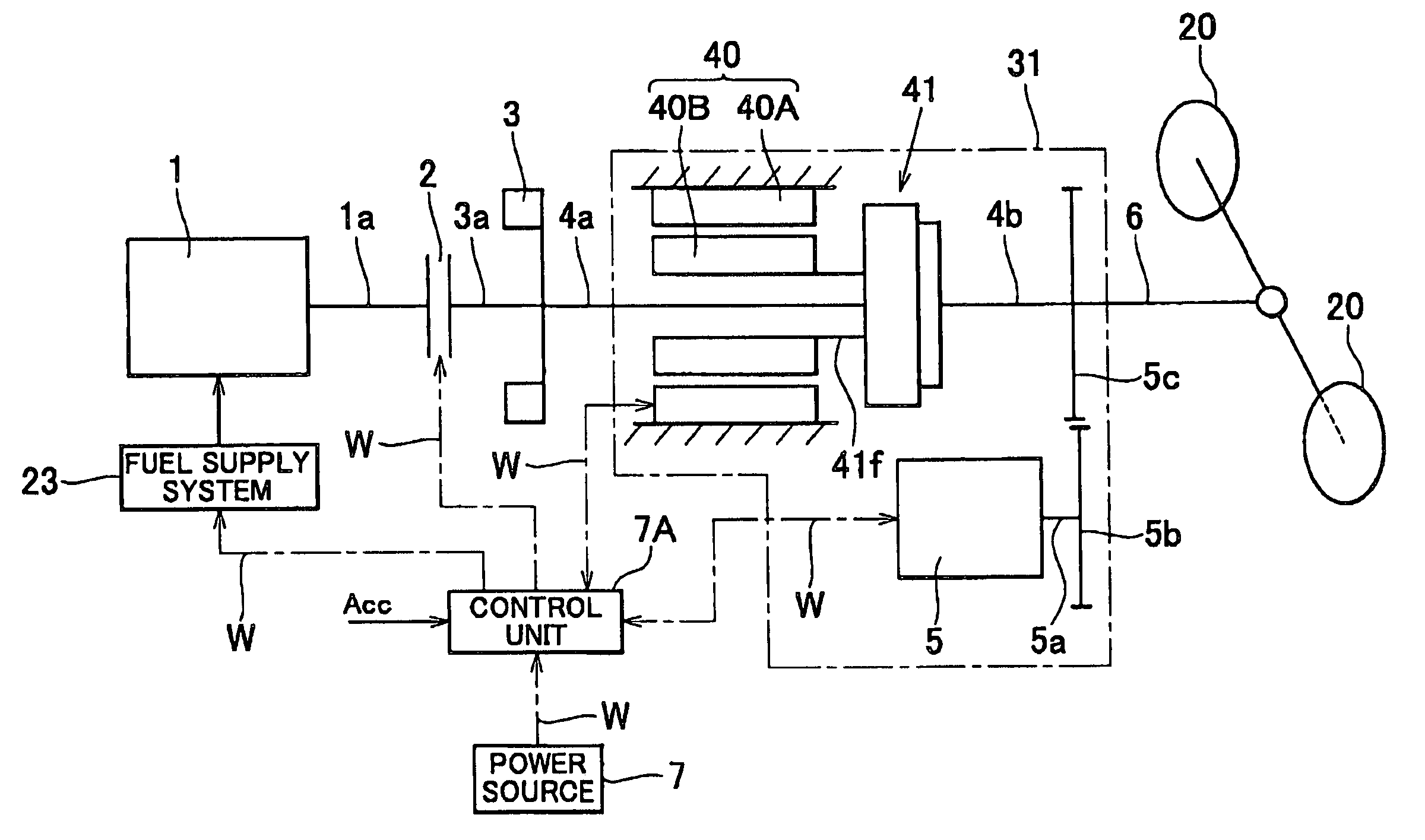
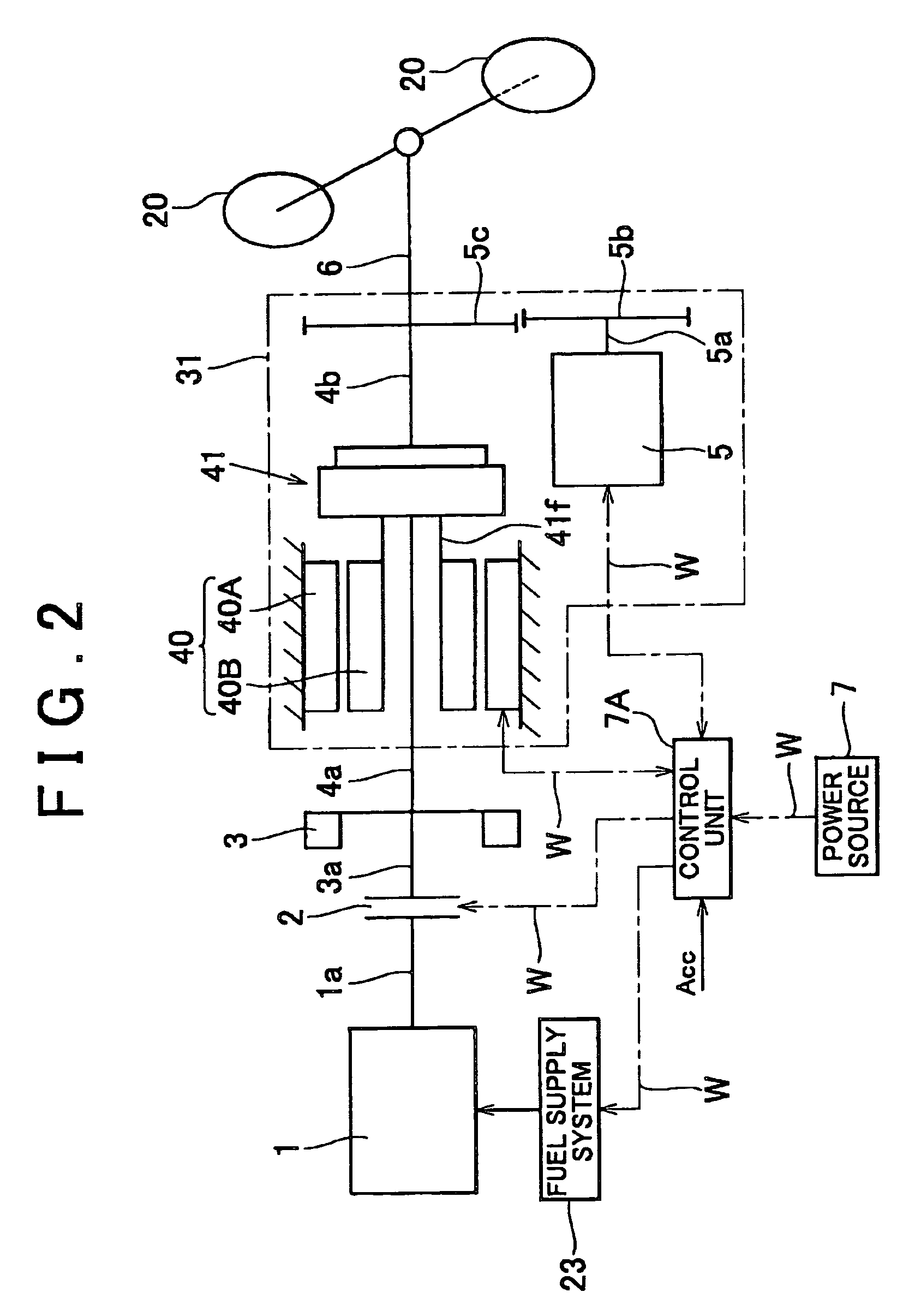
[0055]FIG. 2 illustrates a flywheel energy accumulation / driving system as an example of the vehicle driving apparatus according to the present invention. FIG. 3 illustrates a sample of the inner configuration of a differential gear used in the apparatus in FIG. 2.

[0056]The flywheel energy accumulation I driving system shown in FIG. 2 as an embodiment of the present invention comprises an engine 1, a flywheel 3, a power dividing type power transmission unit 31, an output shaft 6, a control unit 7A and a power source 7. The power dividing type power transmission unit 31...


PUM


Abstract

A method of controlling a vehicle driving system having differential gear including an input shaft, an outlet shaft and a reactionary shaft, a flywheel, an engine, the flywheel and the engine being interlocked with the input shaft, an output shaft interlocked with the outlet shaft, a first motor generator (MG) interlocked with the reactionary shaft and a second MG adapted to receive the output electric power of the first MG as input. If the indicated torque of the output shaft as indicated by the pedaled quantity of the accelerator pedal is T2 and a torque of the reactionary shaft is Trd, while a power transmission efficiency from the input shaft to the reactionary shaft by way of the differential gear, a power transmission efficiency from the input shaft to the output shaft by way of the differential gear and a power transmission efficiency from the reactionary shaft to the output shaft by way of the first MG and the second MG are respectively ηmr, ηmo and ηe, a critical speed ratio of the differential gear, a rotational speed of the output shaft and that of the flywheel are respectively ec, N2 and Nf, the torque Trd is determined by the relation ofTrd=(ec−1)×T2×ηmr / [{ηmo−(ηmr×ηe)}+{(ec×Nf / N2)×ηmr×ηe}]and generation of electric power of the first MG is controlled so as to cause the reactionary shaft to produce the torque Trd.

Description

BACKGROUND OF THE INVENTION[0001]1. Field of the Invention[0002]This invention relates to a method of controlling a vehicle driving system adapted to accumulate power output intermittently from a thermal engine in a flywheel as rotational energy and only a necessary part of the accumulated energy is taken out to the output shaft of a power dividing type power transmission unit. The present invention also relates to a vehicle driving apparatus for driving a vehicle driving system by means of such a control method. Thermal engines to which the present invention is applicable include internal-combustion engines and external-combustion engines. Generally, power dividing type power transmission unit comprises a power dividing mechanism, which may be a type using a motor generator where both an inner rotor and an outer rotor rotate or a type where an ordinary motor generator is connected to the reactionary shaft of a differential gear.[0003]2. Description of the Related Art[0004]Known met...

Claims


Application Information

Patent Timeline
Patent Type & Authority Patents(United States)
IPC IPC(8): B60L11/02B60L50/10B60K6/30B60K6/445B60K6/48
CPCB60K6/30B60W10/06B60W10/08B60W20/00F02N5/04F02N11/04B60L11/14B60L11/16B60L15/20B60K6/48Y02T10/70Y02T10/6221Y02T10/6286Y10S903/96B60L2240/421B60L2240/423B60L2240/441B60L2240/443B60L2240/507B60L2260/22B60L2260/26Y10T477/60Y02T10/7077Y02T10/7027Y02T10/7033Y02T10/7275Y02T10/642Y02T10/72B60L50/16B60L50/30Y02T10/62Y02T10/64Y02T10/7072B60K2006/268B60W20/11
Inventor MIYAO, TAKAYUKI
Owner MIYAO TAKAYUKI
Why Eureka
Try Eureka