Imaging lens

a technology of imaging lens and focusing lens, which is applied in the field of imaging lens, can solve the problems of reducing the size of the lens system, difficult to balance between aberration correction and size reduction, and the back focus distance is too long, so as to achieve excellent optical performance, reduce size and weight, and excellent optical performan

Active Publication Date: 2007-11-13
ENPLAS CORP
View PDF6 Cites 5 Cited by
  • Summary
  • Abstract
  • Description
  • Claims
  • Application Information

AI Technical Summary

Benefits of technology

[0022]In the first aspect of the present invention, the first lens is a meniscus lens having a positive power whose convex surface faces the object side, the second lens which is a meniscus lens having a positive power whose convex surface faces the image surface side, a third lens which is a biconcave lens having a negative power, and a diaphragm is disposed between the first lens and the second lens. In addition, the conditions expressed by each of the expressions (1)–(4) are satisfied. With this, it is possible to reduce the size and weight, maintain an excellent optical performance, improve productivity, and secure high telecentricity and back focus distance. In addition, the shape of the second lens allows balance between peripheral areas and the center area.
[0043]Further, in addition to the effects of the imaging lens according to the first to fifth aspect, the imaging lens according to the sixth aspect can achieve an imaging lens that has more excellent productivity and is more reduced in size and weight.

Problems solved by technology

However, these imaging lens systems cannot handle higher definition and higher resolution that is demanded of the imaging lens system in recent years.
Therefore, it is difficult to balance between aberration correction and size reduction of the lens system.
In addition, the power distribution of first to third lenses and the center radius curvature of both surfaces of the first lens in the lens system in Patent Literature 1 cause the back focus distance to become too long.
As a result, the entire length of the lens system becomes too long.
In addition, as in the lens system in Patent Literature 1, the power distribution of the first to third lenses in the lens system in Patent Literature 2 causes the back focus distance to become too long.
As a result, the entire length of the lens system becomes too long.
Therefore, as in the lens system in Patent Literature 1, it is difficult to balance between aberration correction and reducing the size of the lens system.
In addition, the power distribution of the first to third lenses in the lens system in Patent Literature 3 causes the overall length of the lens system to become too long.
Therefore, the last surface in the end of the optical surface protrudes significantly towards the image surface side, thereby causing a problem when various filters and the like are inserted.
Still further, the power distribution of the first, second, and third lenses in the lens system in Patent Literature 4 causes the entire length of the lens system to become too long.
Therefore, the conventional lens systems are still insufficient for maintaining an excellent optical performance, such as high-definition and high-resolution, while actualizing a further reduction in the size and weight (shortening of the entire length) of the lens system itself.

Method used


Image

  • Imaging lens
  • Imaging lens
  • Imaging lens

Examples


examples

[0110]Next, EXAMPLES of the present invention will be described by referring to FIG. 2 to FIG. 23.

[0111]In the EXAMPLES, F no denotes F number, w denotes a half view angle, and r denotes a center radius curvature. Further, d denotes a distance to the next optical surface, nd denotes the index of refraction to the d line, and vd denotes the Abbe number (d line-based).

[0112]k, A, B, C, and D denote each coefficient in a following expression (10). Specifically, the shape of the aspherical surface of the lens is expressed by the following expression provided that the direction of the optical axis 8 is taken as the Z axis, the direction orthogonal to the optical axis 8 as the X axis (the height direction), the traveling direction of light is positive, k is the constant of cone, A, B, C, and D are the aspherical coefficients, and r is the center radius curvature.

Z(X)=r−1X2 / [1+{1−(k+1)r−2X2}1 / 2]+AX4+BX6+CX8+DX10  (10)

[0113]In the following EXAMPLES, reference code E used for a numerical va...

first example

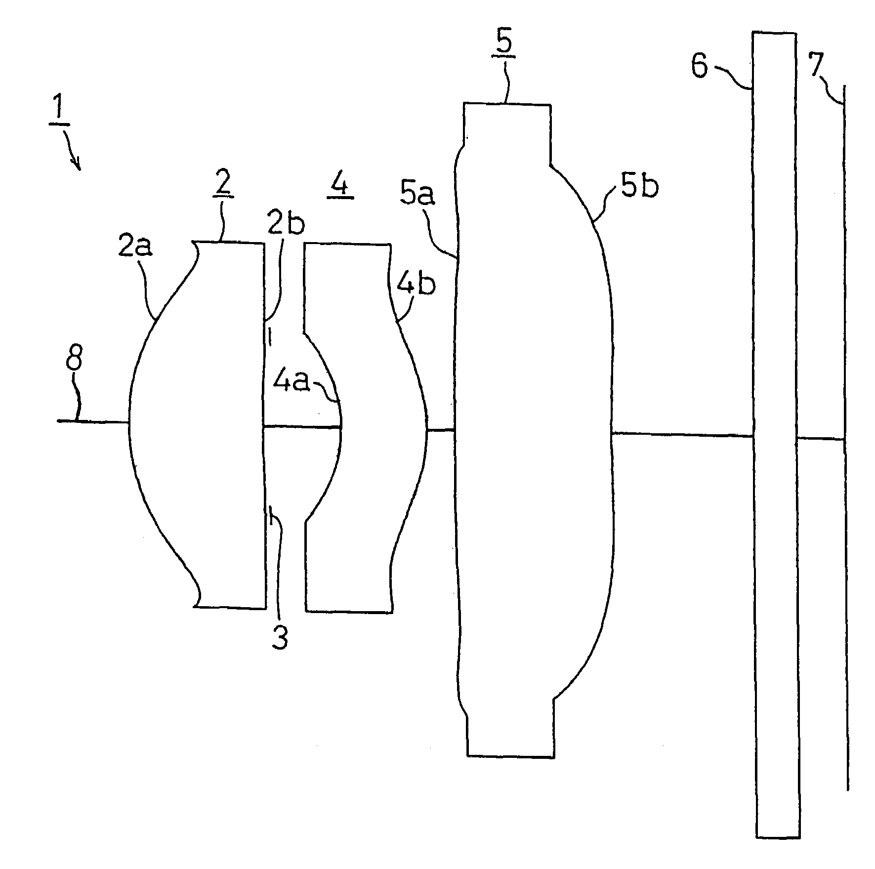
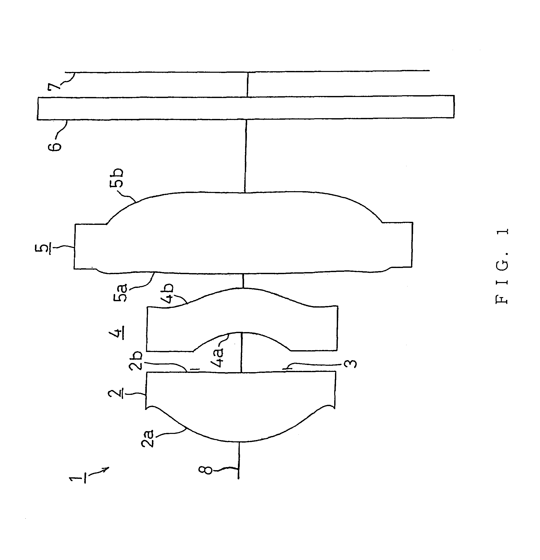
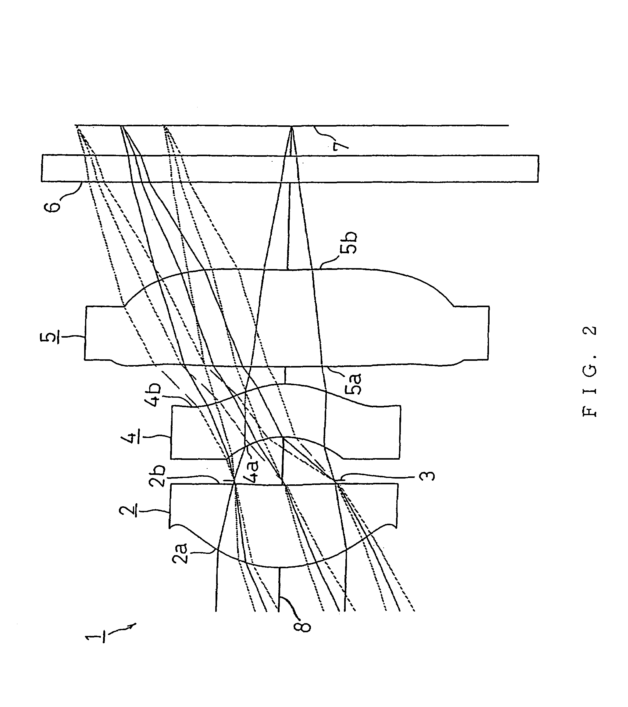
[0114]FIG. 2 shows FIRST EXAMPLE of the present invention. The imaging lens 1 in FIRST EXAMPLE shown in FIG. 2 is the same imaging lens 1 as that shown in FIG. 1.

[0115]The imaging lens 1 of FIRST EXAMPLE was set under the following condition.

[0116]

(Lens Data)fl = 4.14 mm, F no = 2.8Face Numberrdndvd(Object Point)1 (First Face of First Lens)1.430.951.531056.02 (Second Face of First Lens)8.810.053 (Diaphragm)0.000.504 (First Face of Second Lens)−0.920.601.585030.05 (Second Face of Second Lens)−1.120.206 (First Face of Third Lens)−40.981.101.531056.07 (Second Face of Third Lens)9.521.008 (First Face of Cover Glass)0.000.301.516864.29 (Second Face of Cover Glass)0.00(Image Surface)FaceNumberkABCD1−1.03.9E−29.7E−31.8E−2−3.2E−223.0E+1−6.0E−3−2.4E−12.0E−1043.8E−11.8E−12.1E−11.8E−105−4.3E−11.7E−11.1E−1−2.6E−2−3.2E−36−8.4E+13.3E−2−9.9E−3−1.7E−36.1E−471.0E+1−7.4E−21.8E−2−3.0E−32.3E−8Under such conditions, L / fl = 1.19 was achieved, thereby satisfying the expression (1).f1 / fl = 0.739 was achiev...

second example

[0119]FIG. 4 shows SECOND EXAMPLE of the present invention. The imaging lens 1 of SECOND EXAMPLE shown in FIG. 4 was set under the following condition.

[0120]

(Lens Data)fl = 4.12 mm, F no = 2.8Face Numberrdndvd(Object Point)1 (First Face of First Lens)1.460.951.531056.02 (Second Face of First Lens)10.000.053 (Diaphragm)0.000.504 (First Face of Second Lens)−0.910.621.585030.05 (Second Face of Second Lens)−1.110.206 (First Face of Third Lens)−50.001.101.531056.07 (Second Face of Third Lens)11.111.008 (First Face of Cover Glass)0.000.301.516864.29 (Second Face of Cover Glass)0.00(Image Surface)FaceNumberkABCD1−1.03.8E−28.3E−31.7E−2−3.2E−223.4E+1−5.6E−3−2.4E−12.0E−1043.3E−11.8E−12.1E−12.1E−105−4.3E−11.7E−11.1E−1−2.5E−2−2.7E−364.3E+23.2E−2−9.8E−3−1.6E−36.1E−471.6E+1−7.3E−21.8E−2−3.0E−31.2E−5Under such conditions, L / fl = 1.21 was achieved, thereby satisfying the expression (1).f1 / fl = 0.750 was achieved, thereby satisfying the expression (2).f1 / f2 = 0.0512 was achieved, thereby satisfying ...


PUM


Abstract

It is to provide an imaging lens that maintains optical performance and achieves reduction in size and weight. The imaging lens comprises, in order from an object side towards an image surface side, a first lens which is a meniscus lens having a positive power whose convex surface faces the object side, a diaphragm, a second lens which is a meniscus lens having a positive power whose convex surface faces the image surface side, and a third lens which is a biconcave lens having a negative power, wherein the following conditions are to be satisfied; 1.3≧L / fl≧1, 0.8≧f1 / fl≧0.6, 0.12≧f1 / f2>0, −0.1≧f1 / f3≧−0.25 (where, L: entire length of the lens system [distance from the surface of the object side of the first lens to the image taking surface [air reduced length]], fl: focal distance of the entire lens system, f1: focal distance of the first lens, f2: focal distance of the second lens, and f3: focal distance of the third lens).

Description

BACKGROUND OF THE INVENTION[0001]1. Field of the Invention[0002]The present invention relates to an imaging lens and, particularly, to an imaging system of three-lens structure, which is capable of reducing the size and weight. The imaging system is used for an image-taking device that uses an image sensor element such as a CCD, CMOS, etc.[0003]2. Description of the Related Art[0004]Recently, there has been an increasing demand for cameras that utilize an image sensor element such as a CCD, CMOS, or the like, which are mounted on a portable computer, a television phone, a portable phone, and a digital camera, for example. It is demanded that a camera such as this is small and light because the camera is required to be mounted on a limited installation space.[0005]Therefore, it is also necessary for the imaging lens system used for such cameras to be small and light, as is the camera. Conventionally, a single lens structure lens system using a single lens and a two-lens structure sys...

Claims


Application Information

Patent Timeline
Patent Type & Authority Patents(United States)
IPC IPC(8): G02B13/18G02B9/00
CPCG02B13/0035G02B9/12
Inventor SAITO, TOMOHIRO
Owner ENPLAS CORP
Why Eureka
Try Eureka