Radio transmission device and transmission rate decision method

a transmission rate and transmission device technology, applied in the direction of transmission monitoring, frequency-division multiplex, wireless commuication services, etc., can solve the problem of high possibility of communication apparatus to erroneously receive data, and achieve good communication environment

Inactive Publication Date: 2007-11-13
PANASONIC INTELLECTUAL PROPERTY CORP OF AMERICA
View PDF23 Cites 19 Cited by
  • Summary
  • Abstract
  • Description
  • Claims
  • Application Information

AI Technical Summary

Benefits of technology

[0006]In a communication system where a radio transmission apparatus determines a transmission rate of transmission data based on a transmission rate request transmitted from a communication apparatus that is a transmission destination of a packet, when the radio transmission apparatus erroneously receives a transmission rate request, since the transmission apparatus transmits downlink data at a transmission rate determined based on the erroneously received transmission rate request, a possibility is high for the communication apparatus to erroneously receive the data. Accordingly, the reliability of a transmission rate request received in the radio transmission apparatus is an important factor to maintain good communication environments in the communication system.
[0008]In other words, it is an object of the present invention to prevent a communication apparatus from erroneously receiving data transmitted from a radio transmission apparatus even when the radio transmission apparatus erroneously receives a transmission rate request (CQI) transmitted from the communication apparatus that is a transmission destination of a packet, and to maintain the throughput of the entire communication system.

Problems solved by technology

In a communication system where a radio transmission apparatus determines a transmission rate of transmission data based on a transmission rate request transmitted from a communication apparatus that is a transmission destination of a packet, when the radio transmission apparatus erroneously receives a transmission rate request, since the transmission apparatus transmits downlink data at a transmission rate determined based on the erroneously received transmission rate request, a possibility is high for the communication apparatus to erroneously receive the data.

Method used


Image

  • Radio transmission device and transmission rate decision method
  • Radio transmission device and transmission rate decision method
  • Radio transmission device and transmission rate decision method

Examples


embodiment 1

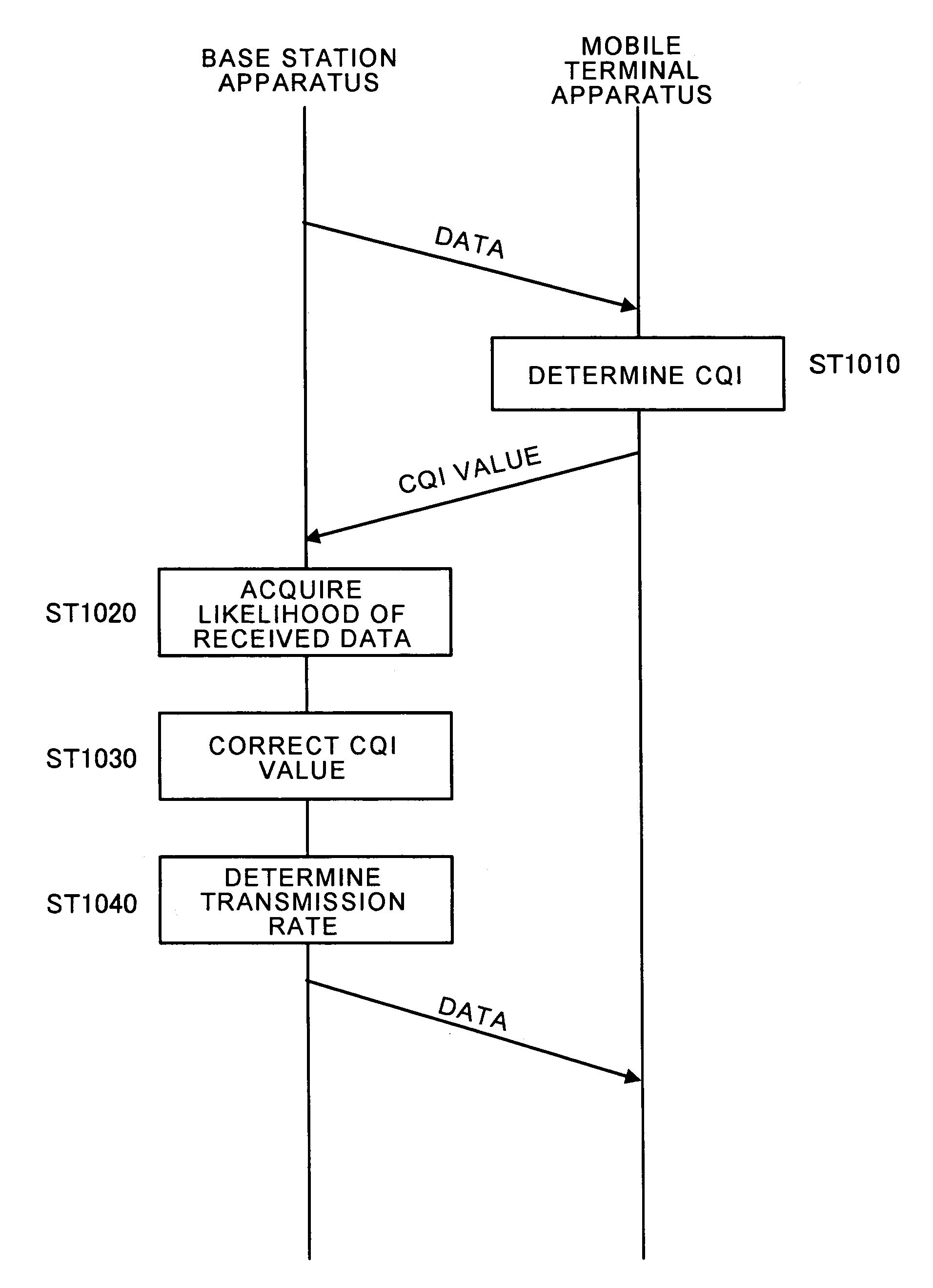
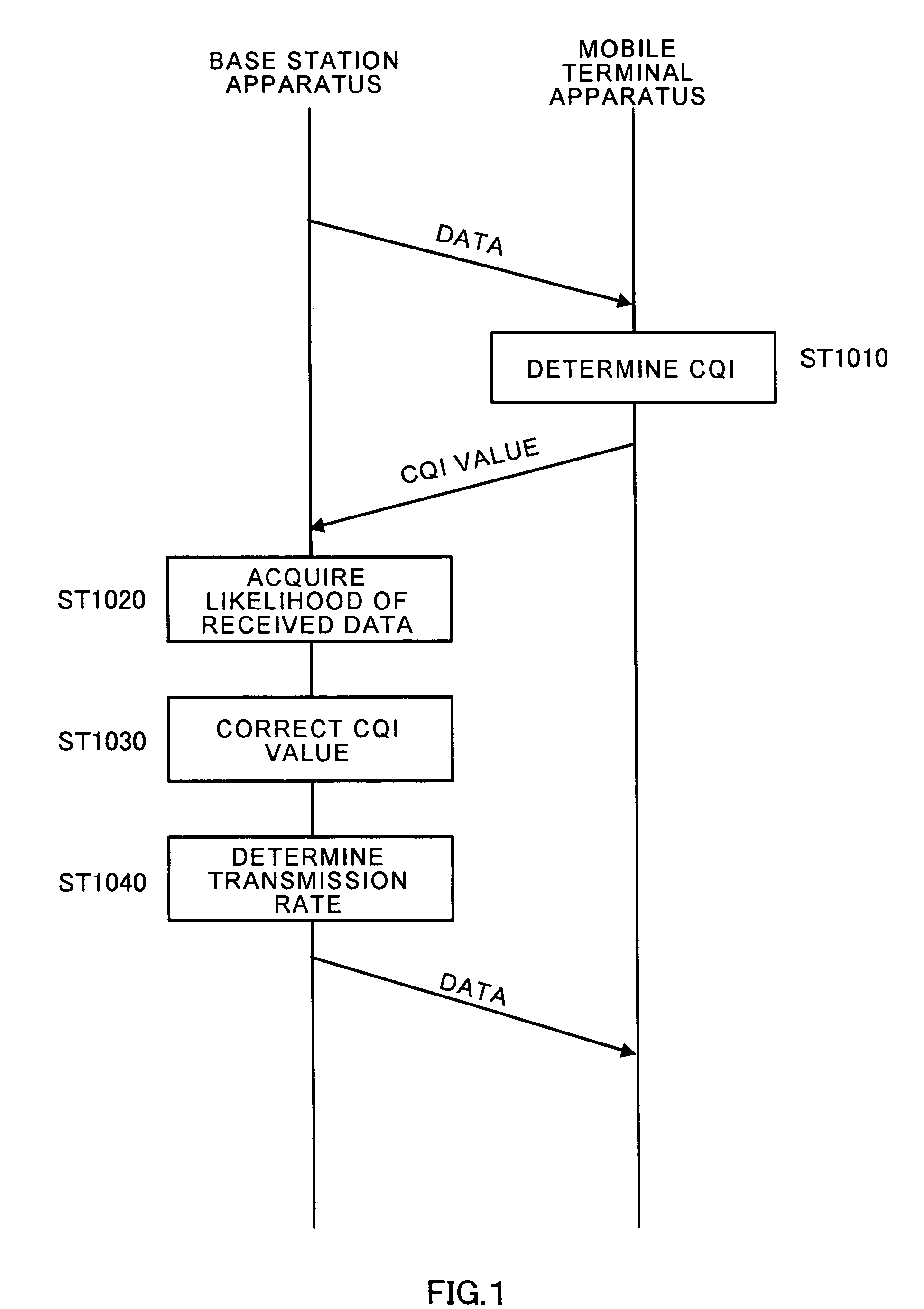
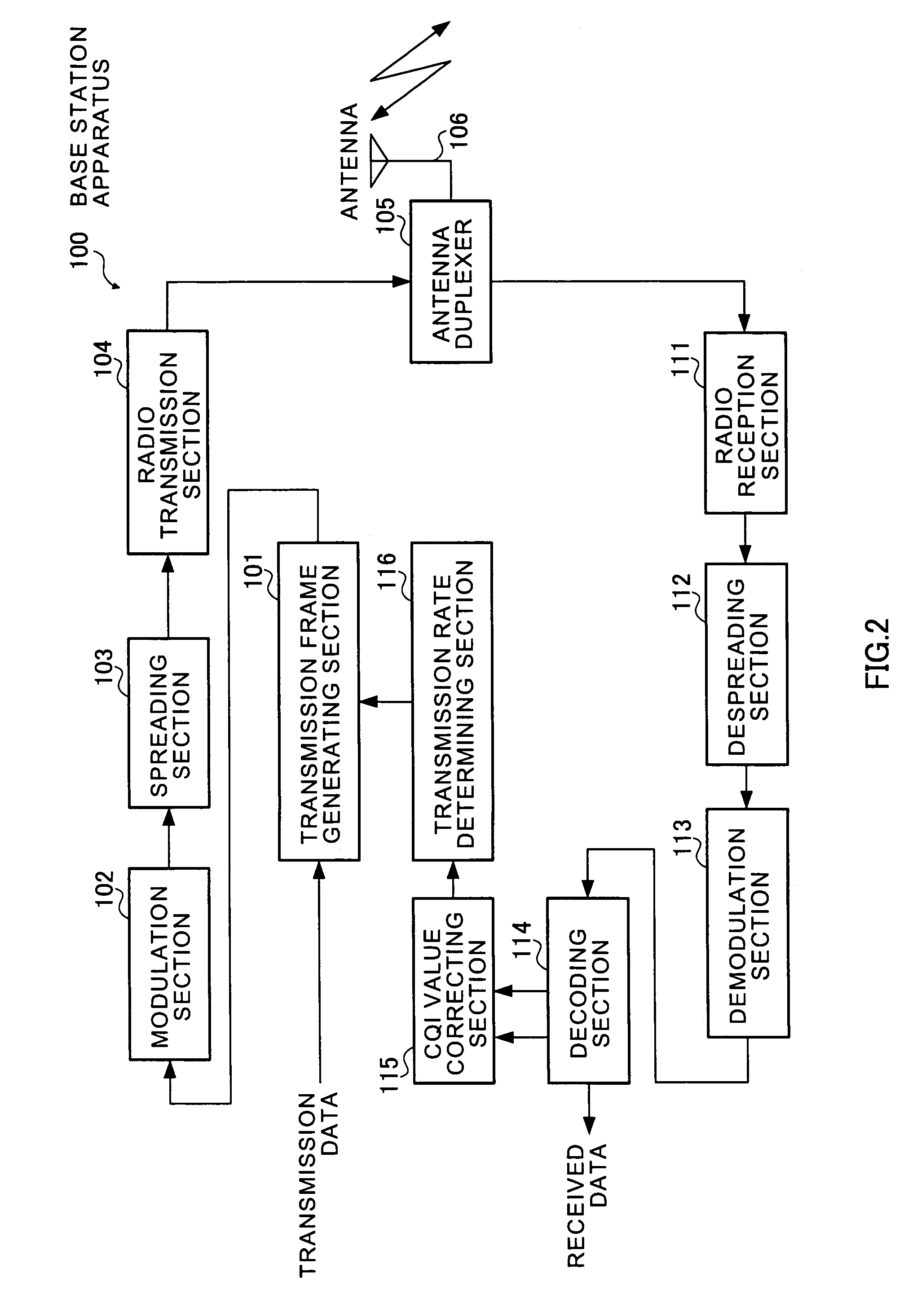
[0028]FIG. 2 is a block diagram illustrating a configuration of base station apparatus 100 according to Embodiment 1 of the invention, and FIG. 3 is a block diagram illustrating a configuration of mobile terminal apparatus 150. Herein, a case is explained as an example where a soft decision value is used as likelihood of received data. In addition, the soft decision value represents amplitude information, phase information, amplitude information and phase information, Euclidean distance from a reference signal point and like after despreading.

[0029]In FIG. 2, base station apparatus 100 has transmission frame generating section 101, modulation section 102, spreading section 103, radio transmission section 104, antenna duplexer 105, antenna 106, radio reception section 111, despreading section 112, demodulation section 113, decoding section 114, CQI value correcting section 115 and transmission rate determining section 116.

[0030]In FIG. 3, mobile terminal apparatus 150 has antenna 151...

embodiment 2

[0045]A base station apparatus according to Embodiment 2 of the invention has the same configuration as that of base station apparatus 100 as shown in FIG. 2 except CQI value correcting section 115a, and only a configuration of the section 115a different from that in Embodiment 1 is shown in FIG. 8. In addition, the same structural elements as in CQI value correcting section 115 as shown in FIG. 4 are assigned the same reference numerals, and descriptions thereof are omitted.

[0046]It is a feature of this Embodiment determining a threshold used in making a determination on likelihood of received data with the threshold based on a CQI value. In other words, a level of originally received CQI value is considered in correcting the CQI value based on the likelihood of received data. When the base station apparatus receives a high CQI from the mobile terminal apparatus, a downlink transmission rate is set high due to the high CQI. Accordingly, when the base station apparatus erroneously r...

embodiment 3

[0055]FIG. 13 is a block diagram illustrating a configuration of base station apparatus 300 according to Embodiment 3 of the invention. In addition, the base station apparatus has a basic configuration similar to that of base station apparatus 100 as shown FIG. 2, and the same structural elements are assigned the same reference numerals to omit descriptions thereof.

[0056]It is a feature of this Embodiment using SIR (Signal-to-Interference Ratio) of a signal received in the base station apparatus.

[0057]In FIG. 13, SIR measuring section 301 measures reception SIR from despread data output from despreading section 112 to output to CQI value correcting section 302. Corresponding to the CQI value output from decoding section 114, CQI value correcting section 302 sets a threshold higher when the CQI value is a high CQI, while setting a threshold lower when the CQI value is a low CQI. Then, the section 302 compares the threshold with the reception SIR output from SIR measuring section 301....


PUM


Abstract

A base station apparatus (radio transmission apparatus) transmits a radio signal of data to a mobile terminal apparatus (communication apparatus of a transmission destination). The mobile terminal apparatus receiving the radio signal determines (ST1010) information (CQI) on a downlink transmission rate enabling reception in the mobile terminal apparatus based on reception quality such as CIR to transmit to the base station apparatus. The base station apparatus extracts a CQI value from the received radio signal, while obtaining likelihood of received data (ST1020), and corrects the CQI value based on the likelihood (ST1030). Then, based on the corrected CQI value, the base station apparatus determines a downlink transmission rate (ST1040). By this means, even when the radio transmission apparatus erroneously receives the transmission rate request transmitted from the communication apparatus of the transmission destination, the communication apparatus is prevented from erroneously receiving the data transmitted from the radio transmission apparatus.

Description

TECHNICAL FIELD[0001]The present invention relates to a radio transmission apparatus used in a wireless communication system for performing high-speed packet transmission, and to a method of determining a downlink transmission rate used in the apparatus.BACKGROUND ART[0002]Developed in the field of wireless communications are systems where a radio transmission apparatus transmits packets at high speed to a communication apparatus that is a transmission destination of the packets, and particularly, downlink high-speed packet transmission systems where a plurality of mobile terminal apparatuses shares a high-speed large-capacity downlink channel, and a base station apparatus transmits packets to the mobile terminal apparatuses. Among the downlink high-speed packet transmission, as a higher packet transmission system of IMT-2000, the system called HSDPA (High Speed Downlink Packet Access) is considered for the purpose of increasing the downlink peak transmission speed, decreasing trans...

Claims


Application Information

Patent Timeline
Patent Type & Authority Patents(United States)
IPC IPC(8): H04Q7/00H04B17/00H04L1/00H04L1/20H04L29/08H04W28/22H04W92/10
CPCH04L1/0026H04L1/0033H04L1/0002H04W92/10H04W28/22
Inventor AIZAWA, JUNICHIIOCHI, HITOSHIMIYA, KAZUYUKI
Owner PANASONIC INTELLECTUAL PROPERTY CORP OF AMERICA
Why Eureka
Try Eureka