Radiation therapy system and method of using the same

a radiation therapy and system technology, applied in the field of radiation therapy systems, can solve the problem of prolonging the time needed to provide the desired dos

Active Publication Date: 2007-11-13
VARIAN MEDICAL SYSTEMS
View PDF6 Cites 61 Cited by
  • Summary
  • Abstract
  • Description
  • Claims
  • Application Information

AI Technical Summary

Problems solved by technology

Rarely, however, can the system jaws alone be used implement a suitable treatment plan.
However, since the x-ray beam emitted from a target is not uniform, it has been necessary to insert a “flattening filter” in the path of the emitted x-rays to achieve beam uniformity.
Because a flattening filter substantially attenuates the average intensity of the x-ray beam, it can prolong the time needed to provide the desired dose.

Method used


Image

  • Radiation therapy system and method of using the same
  • Radiation therapy system and method of using the same
  • Radiation therapy system and method of using the same

Examples


Embodiment Construction

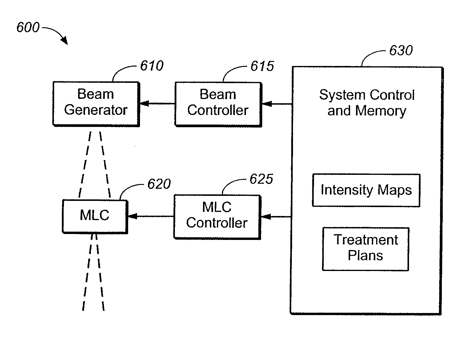
[0018]In general, the preferred embodiment of present invention is directed to method of operating a radiation therapy system having a multileaf collimator without a flattening filter or scattering foil. More generally, the invention is directed to using a multileaf collimator to adjust for substantial unevenness in the intensity of the radiation beam. As described herein, the elimination of the flattening filter facilitates application of higher radiation doses such that treatment times can be reduced. In addition, elimination of the flattening filter allows the therapist to vary the energy of the radiation beam at the same or different portions of the treatment area in real time, thereby increasing the usefulness and flexibility of the system. It will be appreciated that when using an electron or other particle beam it may be desirable to have some type of structure, such as a scattering element, to, for example, broaden the beam. However, in accordance with the present invention ...


PUM


Abstract

A method of using a radiation system having a multileaf collimator (“MLC”) to adjust for unevenness in the radiation emitted by the system is disclosed. By appropriately controlling the MLC in accordance with the invention the system can be operated without a flattening filter. In addition, the invention allows the system user to vary the radiation beam energy in the course of a single treatment, without the need to use or change flattening filters. A map of the uneven radiation beam intensity in the treatment area is obtained, and the map information is combined with a treatment plan to control movement of the leaves of the MLC such that each area receives the correct radiation dose.

Description

FIELD OF THE INVENTION[0001]The present invention is related to radiation therapy systems and is particularly related to a radiation therapy system having a multileaf collimator and a method of using such a system.BACKGROUND OF THE INVENTION[0002]Radiation therapy for cancer treatment has been in use for decades. Modern radiation therapy systems typically generate high intensity x-rays by bombarding a suitable target with high energy electrons. X-rays are emitted from the target in a generally conical pattern, and are initially confined to a generally rectangular beam by moveable, x-ray blocking “jaws” in the head of the system. Typically, the patient is positioned about 1 meter from the x-ray target, and when the jaws are fully open, they define a square treatment area that is about 40 cm×40 cm at the patient plane. However, in many instances it is important to only irradiate a precisely defined area or volume conforming to a tumor, and the target site must be irradiated from multi...

Claims


Application Information

Patent Timeline
Patent Type & Authority Patents(United States)
IPC IPC(8): A61N5/10
CPCA61N5/103A61N5/1042A61N5/1036A61N5/1045
Inventor JOHNSEN, STANLEY W.
Owner VARIAN MEDICAL SYSTEMS
Why Eureka
Try Eureka