
System and method for performing dispersion compensation

a technology of dispersion compensation and optical fiber, applied in multiplex communication, transmission monitoring, instruments, etc., can solve the problems of complex compensation of dispersion in these systems, complicated setup of such a receiver, and various deleterious effects of fiber optic communication systems

Inactive Publication Date: 2007-11-13
GENERAL DYNAMICS ADVANCED INFORMATION SYST INC
View PDF24 Cites 3 Cited by
  • Summary
  • Abstract
  • Description
  • Claims
  • Application Information

AI Technical Summary

Problems solved by technology

Various deleterious effects occur in fiber optic communication systems, such as, for example, the introduction of noise, optical loss, scattering effects, and wavelength dispersion.
Dispersion, however, complicates the set up of such a receiver.
Because dispersion is a wavelength-dependent effect, compensation of dispersion in these systems is complex because some channels may require more compensation than others.
Because dispersion in a typical long-haul system may be as high as ±6000 ps / nm, failure to correct for dispersion may result in total loss of information on the signal.
The aforementioned dispersion compensation problem may be amplified by the increasingly complicated undersea systems.
The conventional methods for compensating for dispersion are expensive and time-consuming and will be essentially obsolete with the increasing complexity of modern DWDM systems.
It requires a considerable amount of labor to compensate each of the signals to provide a bit-error-rate (BER) in excess of 10−12.
One such disadvantage is the introduction of loss to the signal such that additional optical amplifiers may need to be employed in order to compensate for the optical loss.
This adds cost and complexity to the system, as amplifiers themselves are the source of system noise and may also account for additional deleterious effects in the system.
Secondly, only the approximate accumulated dispersion is known beforehand, and thus a time-consuming trial and error approach may be required to determine the appropriate amount of dispersion compensation on a per-wavelength basis.
This may lead to schedule delays and large financial penalties.

Method used


Image

  • System and method for performing dispersion compensation
  • System and method for performing dispersion compensation
  • System and method for performing dispersion compensation

Examples


Embodiment Construction

[0021]The present disclosure will now be described more fully with reference the to the Figures in which various embodiments of the present invention are shown. The subject matter of this disclosure may, however, be embodied in many different forms and should not be construed as being limited to the embodiments set forth herein.

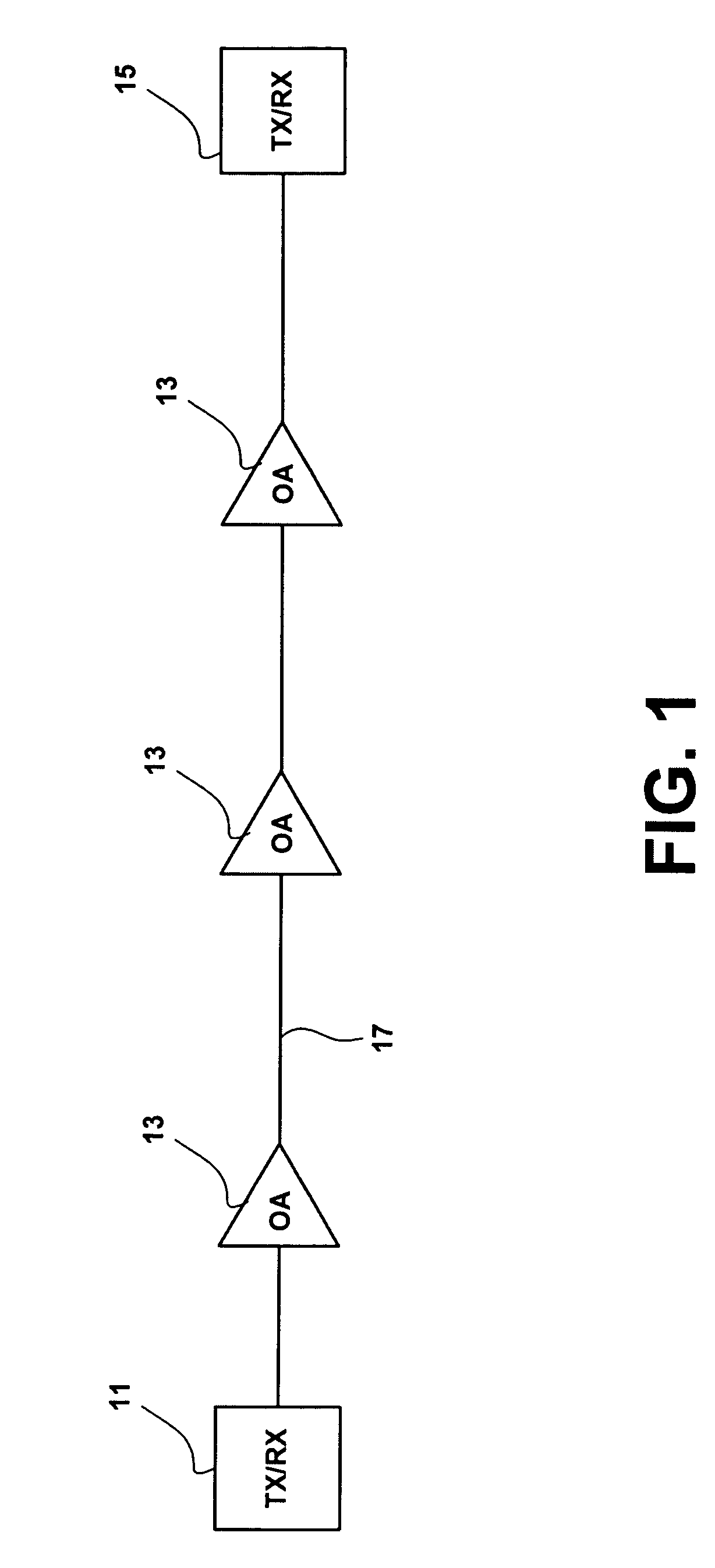
[0022]FIG. 1 shows an optical-fiber based system employing an embodiment of the invention. The optical fiber-based system may be configured to transmit data over the optical fiber link 17. The system may include a first optical transceiver 11, which is configured to both receive and transmit optical signals over the data link. The system may also include a second optical transceiver 15. The system depicted in FIG. 1, may be a bidirectional optical communication system. While a bidirectional system is shown in FIG. 1, one of ordinary skill in the art will understand that an optical system may be unidirectional, and may include a receiver at one end and a trans...


PUM


Abstract

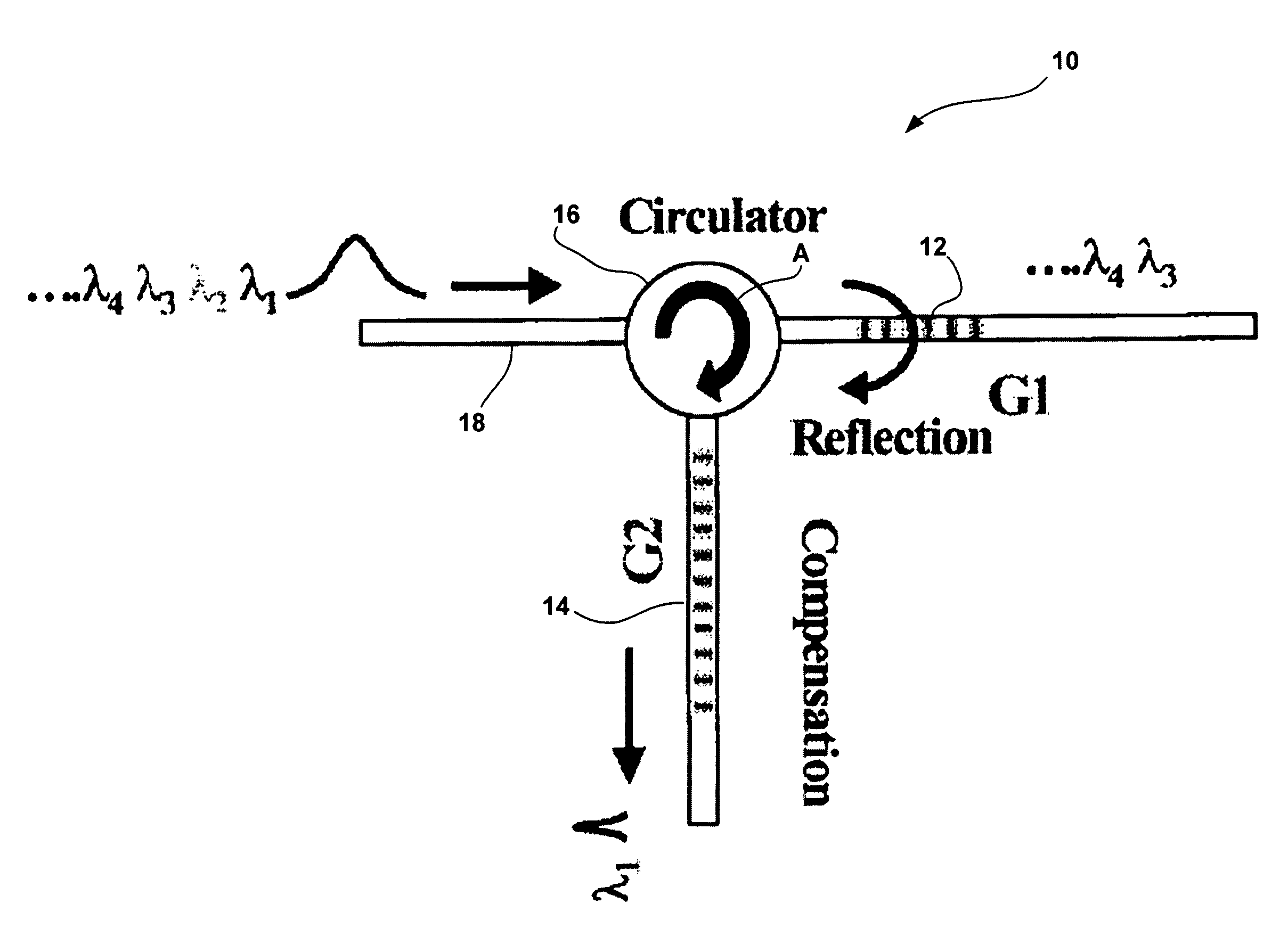
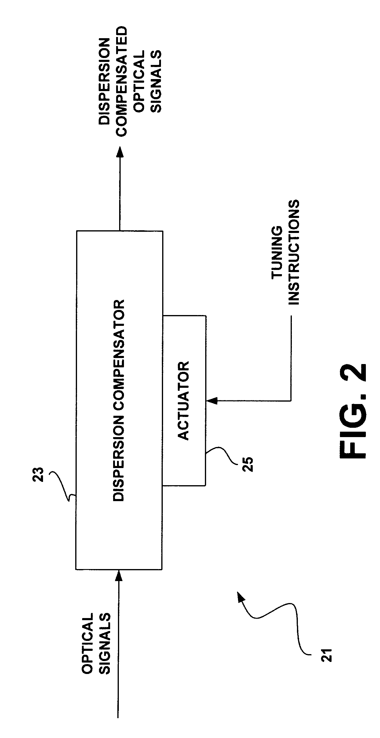
An exemplary embodiment of the present invention includes an optical circulator. The circulator may have, for example, a first port, a second port, and a third port. The first port may be configured to introduce light into the optical circulator. The system may also include a tunable fiber filter Bragg grating connected to the second port of the circulator and a tunable dispersion-compensating fiber Bragg grating connected to the third port of the optical circulator. The tunable dispersion compensating fiber Bragg grating and the tunable fiber filter Bragg grating may be configured to be tuned by a single actuator. This tuning may be either compression or strain tuning.

Description

FIELD OF THE INVENTION[0001]The invention relates to devices for use in optical fiber systems. Particularly, the invention relates to systems and methods for simultaneous wavelength selection and performing dispersion compensation in optical fiber systems.BACKGROUND OF THE INVENTION[0002]Fiber optic communication systems are generally known. There are various types of fiber optic communication systems, including local area networks (LANs), wide area networks (WAN), and various other long-haul fiber optic communication systems. Various deleterious effects occur in fiber optic communication systems, such as, for example, the introduction of noise, optical loss, scattering effects, and wavelength dispersion. One of the last steps in the installation of a long-haul communication system is to configure the terminal receiver to receive the light transmitted over the link. Dispersion, however, complicates the set up of such a receiver. In a system employing a single channel, or a channel l...

Claims


Application Information

Patent Timeline
Patent Type & Authority Patents(United States)
IPC IPC(8): G02B6/28G02B6/26H04J14/02
CPCG02B6/2932G02B6/29322H04B10/2519G02B6/29395G02B6/29394
Inventor WATERS, JAMES P.
Owner GENERAL DYNAMICS ADVANCED INFORMATION SYST INC
Learn More