Liquid cooling system and electronic apparatus using the same

a liquid cooling system and electronic equipment technology, applied in the field of electronic equipment, can solve the problems of insufficient cooling, difficult to maintain the reliability of liquid cooling, and limited use of conventional equipment, and achieve the effect of maintaining corrosion resistan

Inactive Publication Date: 2007-11-20
HITACHI LTD
View PDF7 Cites 3 Cited by
  • Summary
  • Abstract
  • Description
  • Claims
  • Application Information

AI Technical Summary

Benefits of technology

[0017]An object, according to the present invention, is to provide a liquid cooling system enabling to maintain corrosion resistance for a long time period (for example, from 5 to 10 years), and also an electronic apparatus using the same therein.

Problems solved by technology

However, those conventional technologies are limited in the use thereof only in a filed of a large-scaled computer.
This is because the liquid cooling system comes to be large in the scale due to the fact that it needs a large number of parts for exclusive use of cooling, such as a pump, a piping system, a radiator, etc., and it is difficult to maintain the reliability in respect of applying the liquid into cooling thereof.
However, as was mentioned previously, an amount of heat-generation comes up every year, in particular, of the semiconductor elements, etc., which are used in the electronic apparatuses, such as, a personal computer, a home server, a projector, a media storage, etc., and for treating with it, but a compulsive cooling is not sufficient enough, with using the natural air cooling or a fan, or a cooling of using the heat pipe therein.
However, installation of the liquid cooling system into such the computer causes a new problem.
That is, due to the fact that only a small amount of the liquid is held within the liquid cooling system, and further that the operating temperature thereof is relatively high, etc., corrosion is promoted on the parts or elements in contact with the liquid, which are made of a metal material, such as, the heat-receiving jacket and the radiator, since the liquid is degraded in quality thereof even if the corrosive ion flow out in a very small amount thereof, in particular, from the parts or element of an organic material (i.e., the parts or element made of synthetic resin).
If causing water leakage due to the corrosion, it results into an important problem of stopping the function of that electronic apparatus; therefore, it is indispensable to make a treatment of measure of anti-corrosion on the parts or element, to be in contact with the cooling water.

Method used


Image

  • Liquid cooling system and electronic apparatus using the same
  • Liquid cooling system and electronic apparatus using the same
  • Liquid cooling system and electronic apparatus using the same

Examples


example 1

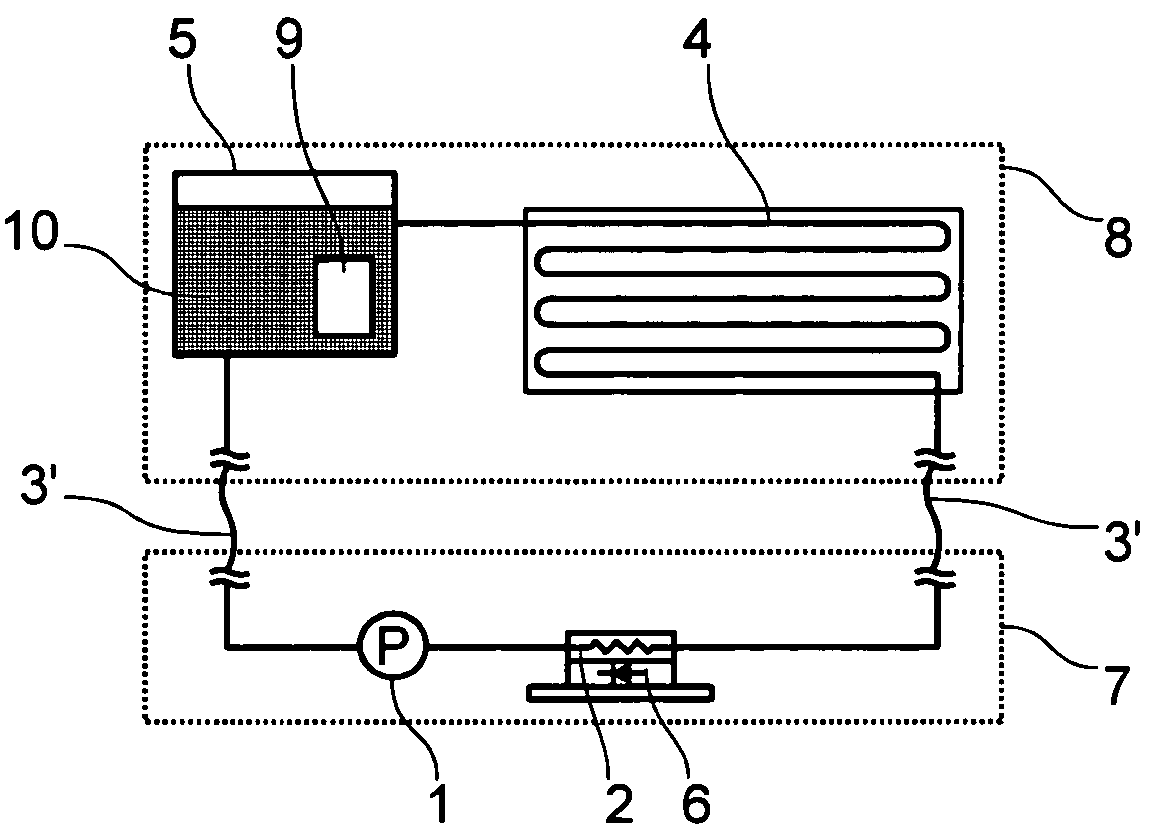
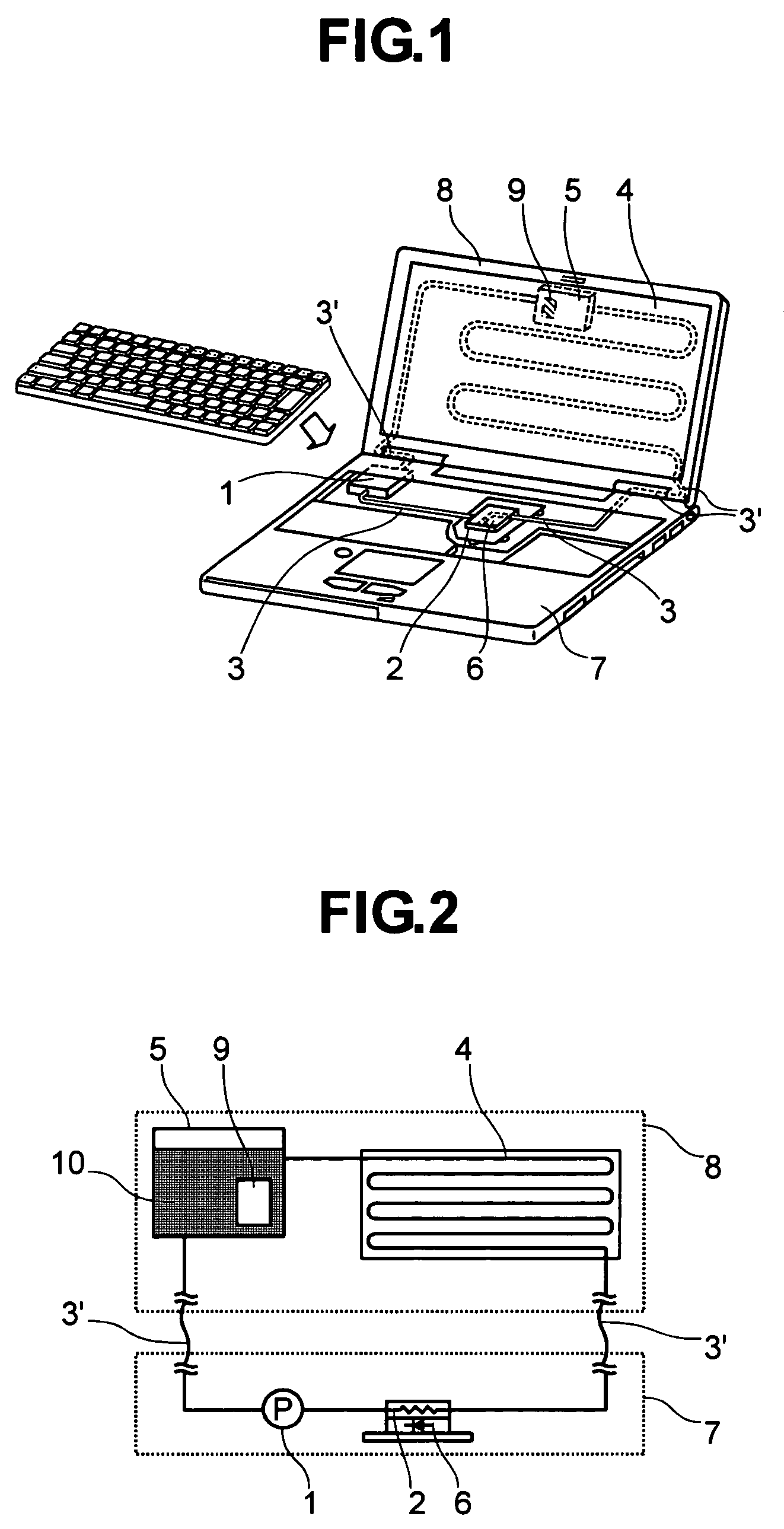
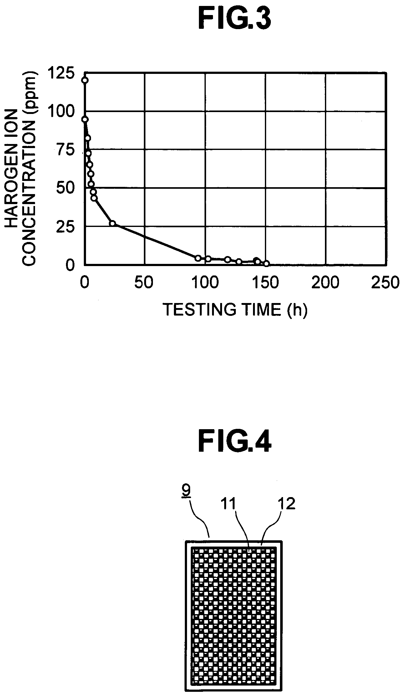
[0049]FIG. 4 is a view for showing an example of the ion exchange bag 9 mentioned above therein.

[0050]In this FIG. 4, the ion exchange bag is made up with an ion exchange resin 11, mixing up a positive ion (i.e., a cation) exchange rein for adsorbing the positive ions and a negative (i.e., an anion) ion exchange resin for adsorbing the negative ions, and a water-permeable bag 12, which contains the ion exchange resins therein and is formed to be rod-like in the shape thereof.

[0051]In other words, like a teabag of green tea or black tea enclosing the tea leaves by the water-permeable cloth or paper, it also encloses the ion exchange resins by the water-permeable cloth or paper, and it is bonded on the periphery thereof, or welded through heating (in FIG. 4, being indicted by a white outlined portion surrounding the ion exchange resin 11).

[0052]This ion exchange bag 9 is effective for ion adsorbing within the cooling water, if putting it into the tank, for example, since almost of the...

example 2

[0057]FIG. 5 is a view for showing the condition, in a case where the ion exchange bag is located at the predetermined position within the tank.

[0058]In this FIG. 5, surrounding the ion exchange bag is provided a partition plate 13.

[0059]With this, the ion exchange bag 9 will not comes up to the surface if a gaseous layer remains in an inside thereof, thereby enabling to adsorb the corrosive ions within the cooling liquid. Also, with provision of the partition plate 13 at the central portion of the tank 5, it is possible to hold the ion exchange bag 9 within the cooling liquid if the cooling system is used in any posture thereof. For this reason, the corrosive ions within the cooling liquid can pass through the water-permeable bag together with the cooling liquid, to be adsorbed by the ion exchange resin within the bag.

example 3

[0060]FIG. 6 is a view for showing other embodiment of the ion exchange bag therein.

[0061]In this FIG. 6, the water-permeable bag 12, having a hole 14 for use of fixing thereof, can be holed within the liquid, but without floating up when a gaseous layer is formed within the bag because of the low water-permeability thereof. For this reason, the corrosive ions within the cooling liquid can pass through the water-permeable bag together with the cooling liquid, to be adsorbed by the ion exchange resin within the bag.


PUM


Abstract

A liquid cooling system is disclosed for use in an electronic apparatus. The system is constructed to be of a reduced size and thickness, thus allowing it to be used for cooling heat-generating devices such as semiconductor elements, while maintaining corrosion resistance. The system includes a pump, a heat-receiving jacket, and flow passages through which the cooling liquid is circulated. An ion exchange bag having a water-permeable bag is disposed within the liquid cooling system. The water-permeable bag further contains an ion exchange resin therein.

Description

BACKGROUND OF THE INVENTION[0001]The present invention relates to an electronic apparatus for cooling a semiconductor element therein, with using a liquid cooling system.[0002]The semiconductor element generates heat during the operation thereof, which is used in an electronic apparatus, such as a computer, etc.[0003]In particular, with the semiconductor in recent year, the heat-generation comes up much more, due to the demands on high processing speed and high capacity or performances thereof. In general, the semiconductor element looses the function of as the semiconductor element, remarkably, when exceeding over a predetermined level in temperature thereof, and therefore it is necessary to make compulsive cooling, in particular, on the semiconductor having a large amount of heat generation thereof.[0004]As a method for cooling down the semiconductor of the electronic apparatus, for example, there are already known methods of applying the heat conduction, applying an air cooling, ...

Claims


Application Information

Patent Timeline
Patent Type & Authority Patents(United States)
IPC IPC(8): F28F7/00F28D15/00H05K7/20F25D17/02G06F1/20H01L23/473
CPCG06F1/203H01L23/473G06F2200/201H01L2924/0002H01L2924/00E01F15/003E01F9/681E01F9/685E01F9/608
Inventor MINAMITANI, RINTAROMATSUSHITA, SHINJIOHASHI, SHIGEOKONDO, YOSHIHIRONAGANAWA, TAKASHISUZUKI, OSAMU
Owner HITACHI LTD
Why Eureka
Try Eureka