Power control apparatus for hybrid vehicle

a technology of power control apparatus and hybrid vehicle, which is applied in the direction of battery/fuel cell control arrangement, machine/engine, battery/cell propulsion, etc., can solve the problems of large output power of motors, large electric energy storage devices, and large high tension elements, so as to increase the regenerated energy of the second motor-generator

Active Publication Date: 2007-11-20
HONDA MOTOR CO LTD
View PDF16 Cites 52 Cited by
  • Summary
  • Abstract
  • Description
  • Claims
  • Application Information

AI Technical Summary

Benefits of technology

[0010]According to the power control apparatus for a hybrid vehicle configured as described above, the second motor-generator can be operated using the electrical power being generated by the first motor-generator in addition to the electrical power dischargeable from the electrical energy storage device. As a result, the front wheels or the rear wheels can be driven by the second motor-generator with an output power which is greater than the electrical power dischargeable from the electrical energy storage device by the electrical power being generated by the first motor-generator. In other words, the output power of the second motor-generator can be greater, without increasing the size of the electrical energy storage device, than in the case in which the second motor-generator is operated merely using the electrical power dischargeable from the electrical energy storage device or the electrical power being generated by the first motor-generator.
[0011]Moreover, the electrical power which can be supplied from the electrical energy storage device and the first motor-generator to the second motor-generator, i.e., the sum of the electrical power dischargeable from the electrical energy storage device and the electrical power being generated by the first motor-generator or the difference between the electrical power dischargeable from the electrical energy storage device and the electrical power being supplied to the first motor-generator, is calculated, and when the sum or the difference is smaller than the output power command for the second motor-generator, the output power command for the second motor-generator is limited by the output power limiting section. As a result, the second motor-generator can be operated in a powering manner while the electrical energy storage device and the first motor-generator are preferably operated in such a manner that, for example, the electrical energy storage device is prevented from being over-discharged, and the first motor-generator is prevented from receiving an excessive electrical generation command.
[0021]According to the power control apparatus for a hybrid vehicle configured as described above, the electrical energy storage device can be charged using the regenerated energy from the second motor-generator in addition to the electrical power being generated by the first motor-generator. As a result, an amount of electrical energy, by which the electrical power chargeable into the electrical energy exceeds the electrical power being generated by the first motor-generator, can be provided by the regenerating operation of the second motor-generator. In other words, the regenerated energy from the second motor-generator can be greater, without increasing the size of the electrical energy storage device, than in the case in which the second motor-generator is operated in a regeneration manner merely depending on the electrical power chargeable into the electrical energy storage device or depending on the electrical power being supplied to the first motor-generator.
[0022]When the electrical power which can be supplied from the second motor-generator to the electrical energy storage device and the first motor-generator, i.e., the sum of the electrical power chargeable into the electrical energy storage device and the electrical power being supplied to the first motor-generator or the difference between the electrical power chargeable into the electrical energy storage device and the electrical power being generated by the first motor-generator is smaller than the regeneration command applied to the second motor-generator, the regeneration command for the second motor-generator is limited by the regeneration limiting section. As a result, the second motor-generator can be operated in a regenerating manner while the electrical energy storage device and the first motor-generator are preferably operated in such a manner that, for example, the electrical energy storage device is prevented from being over-charged, and the first motor-generator is prevented from being supplied with an excessive electrical power.
[0024]According to the power control apparatus for a hybrid vehicle configured as described above, the electrical power being discharged from the second electrical energy storage device can be provided by the regenerated energy from the second motor-generator; therefore, the regenerated energy from the second motor-generator can be increased while the electrical energy storage device and the first motor-generator are preferably operated.

Problems solved by technology

In such a case, problems are encountered in that the electrical energy storage device becomes large, and high tension elements become large.
Moreover, in the above-mentioned hybrid vehicle, because the motor for driving either the front wheels or the rear wheels is driven by merely being supplied with electrical energy from the generator, the output power of the motor is limited by the maximum electrical power of the generator; therefore, a desired output power may not be obtained.

Method used


Image

  • Power control apparatus for hybrid vehicle
  • Power control apparatus for hybrid vehicle
  • Power control apparatus for hybrid vehicle

Examples


Embodiment Construction

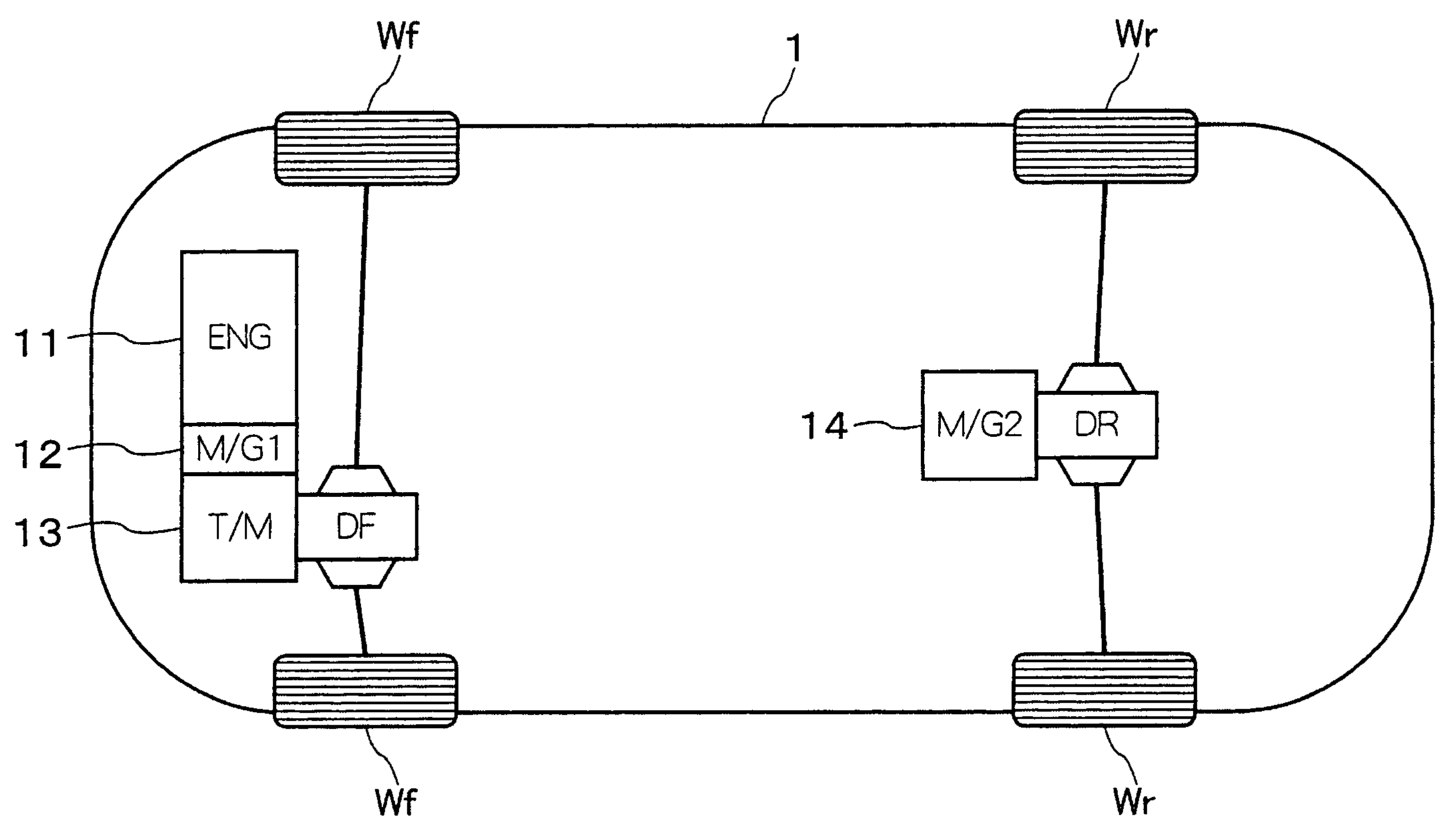
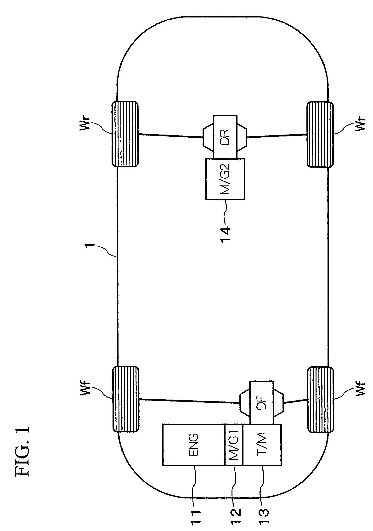
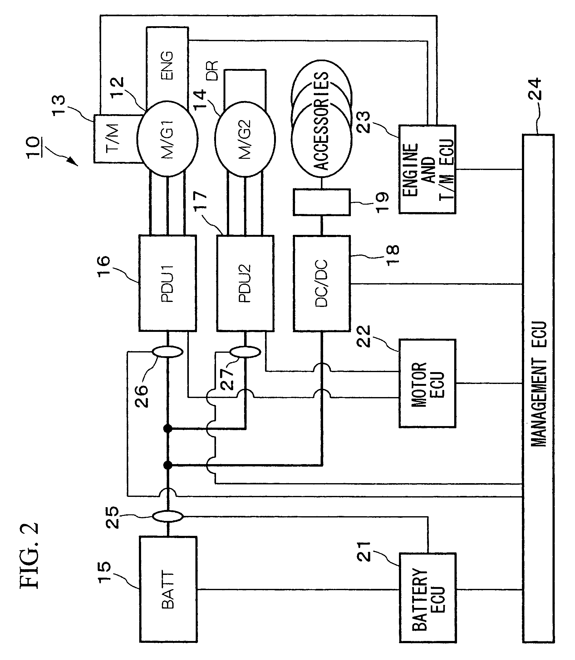
[0031]An embodiment of the power control device for a hybrid vehicle according to the present invention will be explained below with reference to the appended drawings. As shown in FIGS. 1 and 2, the power control device 10 for a hybrid vehicle according to this embodiment is installed in a four-wheel drive hybrid vehicle 1 in which, for example, an internal combustion engine (indicated by ENG in the drawings) 11, a front motor-generator (M / G1) 12, and a transmission (T / M) 13, which are directly connected to each other in series, are connected to front wheels Wf via a front differential gear box DF, and a rear motor-generator (M / G2) 14 is connected to rear wheels Wr via a rear differential gear box DR. The power control device 10 includes a main battery (BATT) 15, a front power drive unit (PDU1) 16, a rear power drive unit (PDU2) 17, a DC-DC converter (DC-DC) 18, an auxiliary battery 19, a battery ECU 21, a motor ECU 22, an engine and T / M ECU 23, and a management ECU 24.

[0032]In the...


PUM


Abstract

A power control apparatus for a hybrid vehicle (1), the hybrid vehicle including an internal combustion engine (11), a front motor-generator (12), and a transmission (13) which are connected to front wheels (Wf), and a rear motor-generator (14) which is connected to rear wheels (Wr) via a rear differential gear box (DR). A calculated value, which is obtained by subtracting a front output power F_POWER and an accessory output power DV_POWER from a battery output power limit B_LimPow is set as an rear output power limit R_LimPow. The smaller of a rear drive command R_PowCmd (which is set depending on the running state of the vehicle) and a rear output power limit R_LimPow is set as a new rear drive command R_PowCmd. Accordingly, a demanded motor output power can be obtained without increasing the size of the main battery (15).

Description

BACKGROUND OF THE INVENTION[0001]1. Field of the Invention[0002]The present invention relates to a power control apparatus for a four-wheel drive hybrid vehicle having an internal combustion engine and a motor as power sources.[0003]2. Description of the Related Art[0004]Conventionally, a power control apparatus for a hybrid vehicle is known in the art, which, for example, includes an internal combustion engine as a power source for driving front wheels, an AC generator that is driven by the internal combustion engine, an electrical energy storage device for storing electrical energy generated by the AC generator, and a motor that drives rear wheels by being supplied with electrical energy from the electrical energy storage device, and in which the amount of generation by the AC generator is controlled depending on the difference between the rotational speeds of the front wheels and the rear wheels (see, for example, Japanese Unexamined Patent Application, First Publication No. Hei ...

Claims


Application Information

Patent Timeline
Patent Type & Authority Patents(United States)
IPC IPC(8): B62D61/10B60K6/44B60W20/00B60K6/52B60K6/54B60L50/15B60L50/16B60W10/08B60W10/26F02D29/02
CPCB60K6/44B60L11/08B60L11/123B60L11/14B60L11/1861B60L11/187B60W10/08B60W10/26B60K6/52Y10T477/23B60L2240/486B60L2260/28B60W20/00B60W2510/244B60W2510/246B60W2520/10B60W2540/10B60W2540/16Y02T10/6217Y02T10/623Y02T10/6265Y02T10/7005Y02T10/7044Y02T10/705Y02T10/7077Y10S903/93B60L50/13B60L50/61B60L50/16B60L58/24B60L58/15Y02T10/62Y02T10/70Y02T10/7072B60W10/24B60W2510/24B60W2510/08
Inventor TATARA, YUSUKESAITO, OSAMUOSHIDA, SHUJIHASEBE, TETSUYA
Owner HONDA MOTOR CO LTD
Why Eureka
Try Eureka